This article's table of contents introduction:

- Table of Contents
- 1. Introduction: What is a 5000 CFH Centrifugal Fan?
- 2. Key Technical Specifications and Design Features
- 3. How Does a 5000 CFH Centrifugal Fan Work?
- 4. Major Application Areas Across Industries
- 5. Comparative Analysis: Forward-Curved vs. Backward-Inclined vs. Radial Blades
- 6. Installation Best Practices for Optimal Airflow
- 7. Maintenance and Longevity Tips
- 8. Frequently Asked Questions (FAQ)
- 9. Conclusion: How to Choose the Right Fan for Your System
** The Ultimate Guide to the 5000 CFH Centrifugal Fan: Performance, Applications, and Selection Criteria
Table of Contents
- Introduction: What is a 5000 CFH Centrifugal Fan?
- Key Technical Specifications and Design Features
- How Does a 5000 CFH Centrifugal Fan Work?
- Major Application Areas Across Industries
- Comparative Analysis: Forward-Curved vs. Backward-Inclined vs. Radial Blades
- Installation Best Practices for Optimal Airflow
- Maintenance and Longevity Tips
- Frequently Asked Questions (FAQ)
- Conclusion: How to Choose the Right Fan for Your System
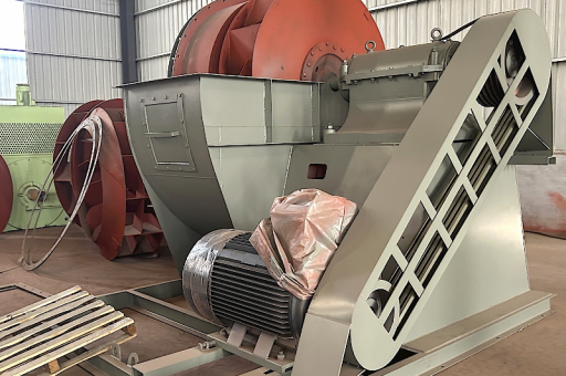
Introduction: What is a 5000 CFH Centrifugal Fan?
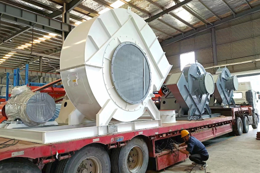
A 5000 CFH centrifugal fan is a medium‑capacity air‑moving device designed to generate a volumetric flow rate of 5,000 cubic feet per hour. In the world of industrial ventilation and process air systems, the term “CFH” (cubic feet per hour) is less common than CFM (cubic feet per minute), but the two are simply related: 5,000 CFH equals approximately 3 CFM. This capacity places the fan in the light‑to‑medium duty range, suitable for small workshops, greenhouse ventilation, fume exhaust in laboratories, and even boosting airflow in wind‑turbine auxiliary cooling circuits.
The centrifugal fan uses a rotating impeller that draws air into the centre and then accelerates it outward by centrifugal force, changing the direction of airflow by 90 degrees. Unlike axial fans, centrifugal designs generate higher static pressure, making them ideal for systems that must overcome duct resistance or filter pressure drops.
Why 5000 CFH? This specific flow rate is often a “sweet spot” for applications where a small axial fan would struggle against backpressure, yet a large industrial blower would be oversized and inefficient. A 5000 CFH centrifugal fan can be powered by a standard fractional‑horsepower motor (typically 1/4 HP to 1/2 HP) and operates quietly enough for indoor use.
Key Technical Specifications and Design Features
When evaluating a 5000 CFH centrifugal fan, the following parameters are critical:
- Flow Rate: 5,000 CFH (83.3 CFM) at free air, often derated to 4,000–4,500 CFH when connected to a typical duct system.
- Static Pressure: Usually in the range of 0 to 3.5 inches of water gauge (in. wg). Higher‑pressure models use backward‑inclined blades; lower‑pressure models use forward‑curved blades.
- Motor Power: 1/4 HP 4‑pole or 1/3 HP 2‑pole motors, with a speed of 1,725 RPM or 3,450 RPM, respectively.
- Sound Level: Between 55 and 70 dB(A) depending on enclosure and speed.
- Material Construction: Steel (painted or galvanised) for general use; stainless steel or aluminium for corrosive or clean‑room environments.
- Inlet/Outlet Sizes: Typically 4‑inch or 5‑inch diameter round inlets, with a 5‑inch by 4‑inch rectangular outlet.
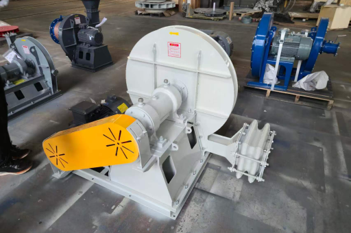
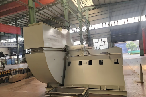
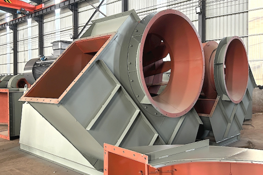
Design Highlight – The Scroll Housing: The volute shape converts the high‑velocity air leaving the impeller into pressure efficiently. A well‑designed scroll minimises turbulence and noise, which is often overlooked in low‑cost fans.
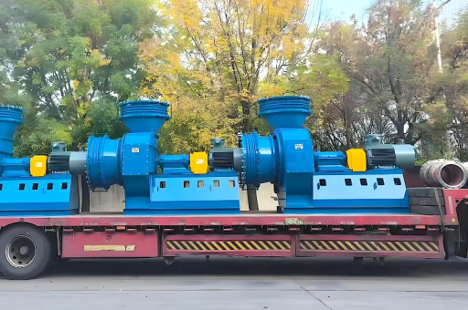
Integration with Wind Turbine Systems: Interestingly, some decentralised wind‑turbine control cabinets use a 5000 CFH centrifugal fan to cool power electronics. The fan’s ability to deliver consistent airflow against the backpressure of fine mesh filters makes it a preferred choice over axial fans in dusty rural environments.
How Does a 5000 CFH Centrifugal Fan Work?
The working principle is rooted in Euler’s pump equation:
- Stage 1 – Air Intake: Air enters the impeller eye axially (along the shaft axis).
- Stage 2 – Centrifugal Acceleration: The rotating impeller blades accelerate the air outward. The kinetic energy of the air increases.
- Stage 3 – Pressure Recovery: As the high‑velocity air enters the volute (scroll casing), the cross‑sectional area increases, causing velocity to drop and static pressure to rise (Bernoulli’s principle).
- Stage 4 – Discharge: Pressurised air exits through the outlet duct.
The 5000 CFH flow rate corresponds to a tip speed of the impeller of about 20–30 m/s for a 6‑inch diameter wheel. A higher tip speed produces higher pressure but also increases noise and power consumption. The fan’s performance curve is a trade‑off between flow and pressure; you never get both at maximum.
Key Equation:
Power consumption (watts) ≈ (Flow in CFM × Static Pressure in in. wg) / (6356 × Fan Efficiency)
For a typical 5000 CFH fan with 2.0 in. wg and 55% efficiency:
Power = (83.3 × 2.0) / (6356 × 0.55) ≈ 047 HP (35 W). This shows that most commercial 5000 CFH fans have motors significantly oversized to handle start‑up loads and filter loading.
Major Application Areas Across Industries
A 5000 CFH centrifugal fan is versatile enough to serve in the following roles:
| Industry | Application | Why Centrifugal? |
|---|---|---|
| Agriculture | Greenhouse air circulation, grain bin aeration | Handles duct resistance from plastic tubing; lower noise near livestock |
| Light Manufacturing | Fume extraction from soldering stations, paint booths | Provides steady negative pressure; filters easily attachable |
| HVAC | Small‑space ventilation for server rooms, basements | Compact size, 90‑degree discharge fits into tight ceiling spaces |
| Renewable Energy | Cooling of wind‑turbine control cabinets or inverters | Reliable under dusty, high‑vibration conditions |
| Laboratories | Chemical fume hood exhaust for small labs | Resistant to corrosive gases when made of stainless steel |
Case Study – Cooling a Wind Turbine Controller:
A 2.3‑kW wind turbine inverter generates approximately 400 W of heat loss. A 5000 CFH centrifugal fan, operating at 0.8 in. wg, moves 83 CFM through a heatsink with a 15°C temperature rise, keeping the IGBTs below 85°C. The fan runs at a lower speed (1,200 RPM) to minimise noise in a residential turbine setup.
Comparative Analysis: Forward-Curved vs. Backward-Inclined vs. Radial Blades
Choosing the right blade design is crucial for the 5000 CFH range:
-
Forward‑Curved (Squirrel‑Cage):
- Highest flow for a given diameter.
- Lower tip speeds → quieter operation.
- Pressure limit: ~2.0 in. wg.
- Best for: Low‑resistance ducts, heating elements, HVAC.
-
Backward‑Inclined:
- Highest efficiency (70–85%).
- Non‑overloading power curve (motor won’t burn out if duct is blocked).
- Pressure limit: up to 5.0 in. wg.
- Best for: Dust‑laden air, high‑static applications, wind‑turbine cooling.
-
Radial (Paddle‑Wheel):
- Self‑cleaning, handles sticky material.
- Lowest efficiency (40–50%).
- Best for: conveying wood chips, granules.
For a 5000 CFH fan in typical ventilation, forward‑curved blades dominate. However, if the system includes filters or long ducts, a backward‑inclined fan may reduce energy costs over time.
Installation Best Practices for Optimal Airflow
To ensure the fan delivers its rated 5000 CFH:
- Straight Inlet Duct: Make sure the fan has at least one duct diameter of straight pipe before the inlet. A 90‑degree elbow right at the inlet can reduce flow by 15–20%.
- Discharge Plenum: If discharging into a plenum, ensure the plenum volume is at least 5 times the CFM (e.g., 415 cubic feet for 83 CFM).
- Vibration Isolation: Use rubber isolation mounts (not rigid metal) to prevent transmitting vibrations to the wind‑turbine tower or building structure.
- Motor Wiring: For 3‑phase motors, ensure the rotation direction matches the arrow on the housing. Single‑phase motors usually have built‑in protection against wrong rotation.
- Filter Selection: A MERV‑8 pre‑filter adds about 0.3 in. wg resistance. Ensure the fan’s spec sheet includes the capacity to handle that additional pressure.
Common Mistake: Using a fan at the far end of a long duct (pull configuration) without a straight inlet causes cavitation‑like flow separation, reducing actual flow below 5000 CFH.
Maintenance and Longevity Tips
A well‑maintained 5000 CFH centrifugal fan can last 10–15 years. Key steps:
- Clean the impeller blades every 6 months (dust build‑up unbalances the wheel, increasing vibrations and bearing wear).
- Check and re‑grease bearings every 2,000 operating hours (if the fan has regreasable sealed bearings).
- Inspect the belt tension (belt‑driven models) – a loose belt reduces RPM and flow; an overtight belt stresses bearings.
- Monitor motor current – an increase of 10% above nameplate indicates a partial blockage or worn bearings.
- Test the capacitor (single‑phase motors) annually, as a weak capacitor reduces starting torque.
For wind‑turbine installations, consider a thermostat‑controlled auto‑start to reduce unnecessary runtime – the fan only runs when the inverter temperature exceeds 45°C.
Frequently Asked Questions (FAQ)
Q1: Can a 5000 CFH centrifugal fan replace a larger axial fan?
A: Not directly. A 20‑inch axial fan may move 5,000 CFH at near‑zero static pressure, but if your system has any ducting or filters, the centrifugal fan will maintain higher flow under resistance. Always match the fan curve to your system curve.
Q2: What is the difference between CFH and CFM?
A: 1 CFM = 60 CFH. So 5,000 CFH = 83.3 CFM. Some manufacturers use CFH for very small fans or low‑flow applications to avoid decimal points.
Q3: Can I use this fan to cool a wind‑turbine inverter?
A: Yes, provided the static pressure of the inverter heatsink and filter is less than the fan’s rated pressure. A 5000 CFH (83 CFM) centrifugal fan is often sufficient for a 2–3 kW inverter.
Q4: How loud is a 5000 CFH centrifugal fan?
A: Typically 55–65 dB(A) at 5 feet, comparable to a dishwasher. Noise can be reduced by slowing the motor with a variable‑frequency drive (VFD) if a lower flow is acceptable.
Q5: What happens if I block the outlet?
A: With forward‑curved blades, the motor current may increase (overloading). With backward‑inclined blades, the current actually decreases. In any case, blocking the outlet for more than a few minutes can overheat the motor. Install a relief damper if blockage is possible.
Conclusion: How to Choose the Right Fan for Your System
The 5000 CFH centrifugal fan is a reliable, compact solution for moving air against moderate resistance. To make the best selection:
- Step 1: Calculate your total system static pressure (duct losses + filter + equipment losses). Use the Darcy–Weisbach equation for ductwork.
- Step 2: Ensure the fan’s performance curve shows at least 5,000 CFH at that pressure (not at free air).
- Step 3: Choose blade type: forward‑curved for low noise and size, backward‑inclined for efficiency and filter loading.
- Step 4: Verify the environmental rating (IP54 for outdoor wind‑turbine use, or explosion‑proof for flammable fumes).
- Step 5: Factor in a safety margin of 10–15% on flow to account for future filter loading.
Final thought: In the growing field of decentralised renewable energy, the humble 5000 CFH centrifugal fan plays a quiet but vital role – ensuring that control electronics inside a wind‑turbine nacelle remain cool, even on the hottest summer day. By understanding its design, application, and limitations, you can harness its full potential for your ventilation or cooling project.