** The Ultimate Guide to 130,000 m³/h Dust Collector Exhaust Fans: Specs, Applications, and Performance Optimization

Table of Contents
- Introduction: Why the 130,000 m³/h Rating Matters
- Technical Specifications and Design Features
- Core Applications Across Heavy Industries
- Q&A: Critical Performance and Selection Questions
- Energy Efficiency and Cost-of-Ownership Analysis
- Installation Best Practices for High-Volume Systems
- Maintenance Strategies to Ensure Long-Term Reliability
- Conclusion: Matching System Demand with Fan Capability
Introduction: Why the 130,000 m³/h Rating Matters
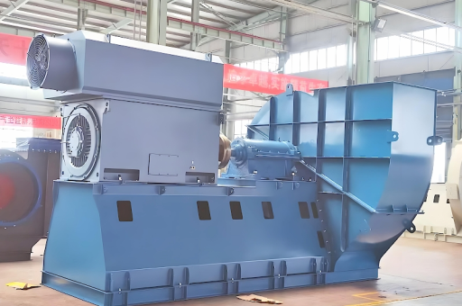
In dust collection systems, the exhaust fan is the heart of the operation. A 130,000 m³/h dust collector exhaust fan represents a specific high-capacity tier designed for medium to heavy industrial environments. "130,000 m³/h" defines the volumetric airflow rate—the volume of air the fan can move in one hour under standard operating conditions. This capacity is not arbitrary; it is typically matched to dust collectors handling multi-bin cyclones, baghouse filters, or cartridge systems that extract fumes, particulates, and airborne contaminants from large production lines.
Industries from woodworking to cement processing rely on this airflow intensity to maintain negative pressure in duct networks and ensure captured dust is transported efficiently to collection points. Without the correct exhaust fan, the entire dust control system fails. Selecting a 130,000 m³/h unit means balancing static pressure requirements, impeller design, motor power, and noise constraints—all of which this guide will unpack.
Technical Specifications and Design Features
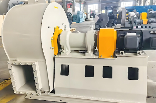
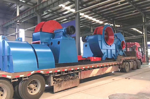
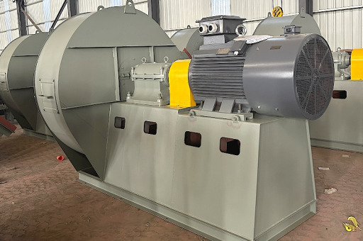
A standard 130,000 m³/h dust collector exhaust fan (often referred to as an ID or induced draft fan in centralized systems) includes these core elements:
- Airflow: 130,000 m³/h (approximately 76,500 CFM) at fan inlet conditions.
- Static Pressure Capacity: Typically in the range of 1,500–3,000 Pa, depending on duct resistance and filter loading.
- Impeller Type: Backward curved or airfoil blades designed for high efficiency and low dust buildup.
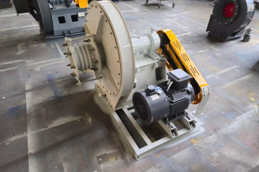
- Drive System: Direct drive or belt-driven with VFD compatibility for variable speed control.
- Motor Power: Ranges from 75 kW to 150 kW based on pressure requirements.
- Housing Material: Carbon steel with epoxy coating, or stainless steel for corrosive environments.
- Inlet/Outlet Configurations: Standard rectangular or circular flanges for duct connection.
Modern units often feature a fan with integrated monitoring ports for pressure and vibration sensors. The blade geometry is critical: backward inclined fans offer higher efficiency, while radial blades handle heavy dust loads but create more noise. For 130,000 m³/h applications, the impeller diameter frequently exceeds 1,200 mm, requiring robust bearings and shaft stiffening.
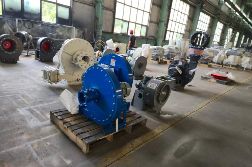
Core Applications Across Heavy Industries
The 130,000 m³/h exhaust fan is not a one-size-fits-all device. It serves specific processes:
- Woodworking Facilities: Centralized chip and dust extraction systems in panel production, CNC routing, and sanding lines. This flow rate supports networks with up to 50–80 pick-up points.
- Cement and Mineral Processing: Ventilation of grinding mills, bag packers, and conveyor transfer points where high dust loads demand reliable negative pressure.
- Metal Fabrication and Welding: Exhausting welding fumes, plasma cutting smoke, and abrasive blasting dust through large canopy hoods.
- Agricultural Grain Handling: Pneumatic conveying or dust control in silo loading/unloading areas, especially in grain elevators dealing with combustible dust.
- Pharmaceutical and Chemical Manufacturing: Containment of fine powders under strict explosive atmosphere (ATEX/NFPA) norms, often with explosion-proof motors and spark-resistant construction.
In each case, the 130,000 m³/h fan must be paired with an appropriately sized dust collector (such as a baghouse with 2,000–5,000 ft² of filter media) to prevent overloading the fan with dirty air.
Q&A: Critical Performance and Selection Questions
Q1: Is the 130,000 m³/h rating measured at actual or standard conditions?
A: Most manufacturers rate fans at standard air conditions (20°C, 101.325 kPa, 50% RH). If your system operates at higher altitudes or temperatures, correct to actual conditions. For example, at 80°C and 1,000 m altitude, effective airflow may drop to ~110,000 m³/h. Always specify actual inlet conditions when ordering.
Q2: How do I calculate the required static pressure for my system?
A: Total pressure loss = duct friction loss + filter pressure drop + equipment losses. A typical 130,000 m³/h baghouse might add 1,200–1,800 Pa when clean and up to 2,500 Pa when filters are loaded. Ductwork of 100 m length with multiple elbows adds 400–800 Pa. Your fan curve must intersect system curve at 130,000 m³/h and the combined static pressure.
Q3: Can I retrofit an existing system with a 130,000 m³/h fan?
A: Yes, but verify existing duct diameter, motor power supply, and structural supports. A larger fan may require reinforced foundations to handle vibratory forces exceeding 5 kN. Always conduct a fan performance test before and after installation.
Q4: What noise levels should I expect?
A: A backward curved fan at this flow rate typically produces 85–95 dB(A) at 1 m distance. Options include acoustic enclosures, silencers on inlet/outlet, and low-noise blade profiles. For compliance with OSHA or EU workplace noise directives, engineering controls are essential.
Q5: How often should I balance the impeller?
A: After initial installation and every 6 months for continuous heavy-duty service. Unbalance beyond ISO 1940 G6.3 grade can reduce bearing life by 40%.
Energy Efficiency and Cost-of-Ownership Analysis
A 130,000 m³/h exhaust fan operating continuously for 8,000 hours/year at 110 kW motor load consumes over 880,000 kWh annually. At $0.10/kWh, yearly electricity costs exceed $88,000. Improving fan efficiency by just 5% saves over $4,400/year—equivalent to the cost of a premium motor in two years.
Key efficiency factors:
- Impeller Design: Airfoil blades are 8–12% more efficient than flat radial blades at this flow volume.
- Variable Frequency Drives: Reducing speed by 20% cuts power consumption by nearly 50% (affinity laws). For systems with fluctuating load (e.g., shift-based production), VFD payback often occurs within 18 months.
- Filter Maintenance: Dirty filters increase static pressure; every 100 Pa excess pressure adds 1.5–2% to fan power draw.
- Duct Design: Smooth bends and gradual expansions reduce losses. Every 100 Pa saved in ductwork lowers annual energy cost by ~$1,200.
If the fan is belt-driven, check belt alignment monthly; misalignment can waste 3–5% of motor energy.
Installation Best Practices for High-Volume Systems
- Foundation: Pour concrete base minimum 300 mm thick, with vibration isolation pads. Mass should be at least 3x fan weight to dampen resonance.
- Duct Connection: Use flexible connectors (e.g., neoprene canvas) to isolate thermal and mechanical expansion. Never hard-mount ducting to the fan casing.
- Inlet Straight Run: Provide 2–3 duct diameters of straight pipe before the fan inlet. A 130,000 m³/h fan with 1.2 m diameter inlet needs at least 2.4 m of straight duct to avoid flow distortion and efficiency loss.
- Electrical: Install VFD in a dedicated NEMA 4X enclosure with forced cooling. Confirm motor winding thermistors are connected to the drive protection circuit.
- Commissioning: Measure actual airflow using a Pitot traverse in the duct. Compare against fan curve; if flow is below spec, check for blocked filters, closed dampers, or incorrect rotation direction.
Maintenance Strategies to Ensure Long-Term Reliability
- Weekly: Check vibration levels using a hand-held meter. Increase thresholds >7 mm/s RMS indicate imbalance or bearing wear.
- Monthly: Inspect belt tension (deflection method); replace belts in sets to avoid uneven load.
- Quarterly: Lubricate bearings per manufacturer schedule (e.g., greasing intervals based on bearing type and speed). For 130,000 m³/h fans with rolling element bearings, every 750 operating hours is typical.
- Annually: Disassemble and clean impeller blades. Dust buildup on back sides of blades can reduce airflow by 10–15% and cause imbalance. Re-balance impeller if correction weight exceeds 50% of original.
- Pressure Monitoring: Install a differential pressure gauge across the dust collector filters. When delta-P reaches 2,500 Pa, trigger cleaning sequences or bag replacement—this prevents fan overload.
Proactive maintenance extends fan life to 15–20 years, whereas neglect can cause catastrophic failure within 2–3 years.
Conclusion: Matching System Demand with Fan Capability
A 130,000 m³/h dust collector exhaust fan is a precision-engineered component that defines the success of industrial dust management. Its high airflow capacity supports large-scale operations, but only when paired with proper duct design, energy-efficient motors, and rigorous maintenance routines. Whether you are retrofitting an existing line or designing from scratch, understanding the interplay between static pressure, impeller geometry, and operational cost is non-negotiable.
The data-driven approach—validating fan curves on site, optimizing filter schedules, and leveraging VFDs—ensures that the 130,000 m³/h rating translates into actual capture efficiency rather than theoretical bandwidth. For facility managers and engineers, this fan is not just a commodity; it is a system asset that, if selected and cared for correctly, pays dividends through productivity and regulatory compliance.