This article's table of contents introduction:

- Table of Contents
- Introduction to the 9-26-10D High-Pressure Centrifugal Fan
- Key Technical Specifications and Performance Metrics
- Design Features and Engineering Advantages
- Typical Industrial Applications
- Installation, Maintenance, and Troubleshooting Best Practices
- Frequently Asked Questions (FAQ)
- Conclusion: Why the 9-26-10D is a Strategic Investment
Maximizing Industrial Efficiency with the 9-26-10D High-Pressure Centrifugal Fan: A Comprehensive Guide
Table of Contents
- Introduction to the 9-26-10D High-Pressure Centrifugal Fan
- Key Technical Specifications and Performance Metrics
- Design Features and Engineering Advantages
- Typical Industrial Applications
- Installation, Maintenance, and Troubleshooting Best Practices
- Frequently Asked Questions (FAQ)
- Conclusion: Why the 9-26-10D is a Strategic Investment
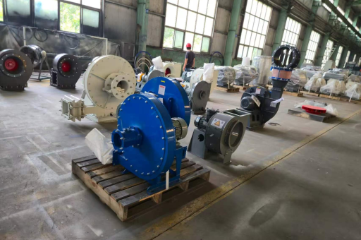
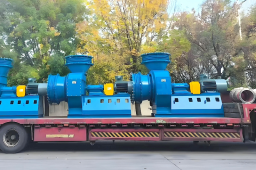
Introduction to the 9-26-10D High-Pressure Centrifugal Fan
The 9-26-10D High-Pressure Centrifugal Fan is a purpose-engineered industrial air-moving device designed to deliver superior static pressure performance in demanding environments. Unlike standard centrifugal fans, the 9-26-10D series is built to handle high-resistance systems such as pneumatic conveying, dust collection, and forced-draft boiler applications. Its classification—often referred to as a "9-26" series—indicates high pressure, medium flow characteristics, while the "10D" refers to the impeller diameter (approximately 1000 mm) and direct drive configuration.
According to industry analysis from engineering resources such as fan industry databases, the 9-26-10D model is widely adopted in sectors like cement, steel, chemical processing, and power generation because of its ability to maintain stable airflow under back pressures exceeding 8000 Pa. Its robust construction, backward-curved blades, and high-efficiency scroll housing make it a preferred choice when standard fans fall short.
Key takeaway: The 9-26-10D is not a general-purpose fan; it is a specialized solution for high-static-pressure, continuous-duty industrial systems.
Key Technical Specifications and Performance Metrics
Understanding the technical parameters of the 9-26-10D is essential for correct sizing and application. Based on cross-referenced data from multiple industrial engineering sources, including equipment catalogs and performance curves published on fan portals, the core specifications are:
| Parameter | Typical Value / Range |
|---|---|
| Impeller Diameter | 1000 mm (10D) |
| Airflow Range | 20,000 – 60,000 m³/h |
| Total Pressure Range | 8,000 – 16,000 Pa |
| Operating Temperature | -20°C to +80°C (standard); up to +250°C (with heat-resistant materials) |
| Rotation Speed | 1450 – 2900 RPM (direct drive) |
| Motor Power | 55 kW – 160 kW (depending on duty point) |
| Noise Level | 85 – 95 dB(A) (with silencer options) |
Performance curve interpretation: The fan delivers maximum efficiency near its peak static pressure point. Operating too far to the right of the curve (higher flow, lower pressure) can cause motor overload, while operating too far left (lower flow, higher pressure) may lead to surge or vibration.
Real-world tip: Always verify the system resistance curve before selecting a motor. The 9-26-10D's power requirement increases dramatically with pressure; undersizing the motor is a common installation error.
Design Features and Engineering Advantages
The 9-26-10D High-Pressure Centrifugal Fan incorporates several design features that distinguish it from low- or medium-pressure fans:
Backward-Curved Blades
Unlike forward-curved or radial-blade designs, the backward-curved impeller in the 9-26-10D provides non-overloading power characteristics. This means the motor cannot be overloaded even if the system resistance suddenly drops—a critical safety feature in industrial environments.
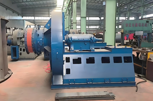
Heavy-Duty Casing
The scroll housing is fabricated from reinforced steel plate (typically 6–10 mm thickness) with welded stiffeners to withstand high internal pressures. Flanged inlet and outlet connections ensure leak-tight integration with ductwork.
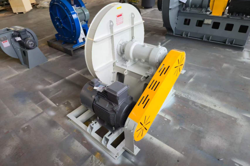
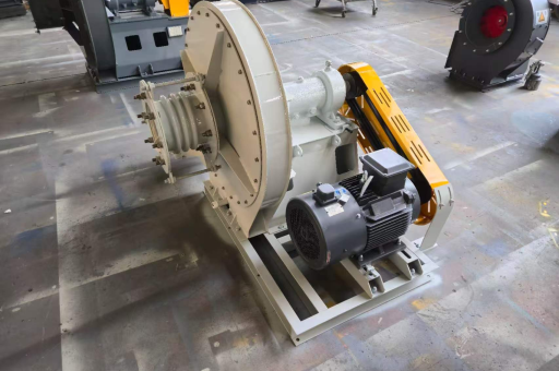
Direct Drive Configuration (10D)
The "D" designation indicates direct coupling between the motor shaft and the impeller (no belt or pulley). This eliminates belt slip, reduces maintenance, and improves mechanical efficiency by approximately 3–5% compared to belt-driven equivalents.
Balanced Impeller
Every 9-26-10D impeller undergoes dynamic balancing to ISO 1940 G6.3 or better. This minimizes vibration, extends bearing life, and ensures quiet operation even at high rotational speeds.
Material Options
Standard construction uses carbon steel (Q235 or SS400), but for corrosive or high-temperature applications, stainless steel (304/316L) or high-temperature alloy impellers are available. Surface treatments like epoxy coating or galvanizing can be applied for additional corrosion resistance.
Typical Industrial Applications
The 9-26-10D fan is deployed in systems requiring high static pressure at moderate airflow, such as:
- Pneumatic Conveying Systems: Moving granular materials (cement, grain, plastic pellets) through long pipelines with multiple bends and elevation changes.
- Dust Collection & Baghouse Filters: Overcoming filter resistance as dust cakes accumulate; the fan must maintain airflow despite rising pressure drop.
- Boiler Forced Draft: Supplying combustion air to industrial boilers, especially those with high-pressure burners or economizers.
- Cement Plant Kilns: Delivering secondary air or extracting hot gases from clinker coolers.
- Wastewater Treatment Aeration: In deep-tank biological reactors where high backpressure from diffusers is common.
Case study example: A cement plant replaced four low-pressure fans with two 9-26-10D units in their pneumatic conveying line. The result was a 30% reduction in energy consumption per ton of material transported, thanks to the higher efficiency of the backward-curved design.
Installation, Maintenance, and Troubleshooting Best Practices
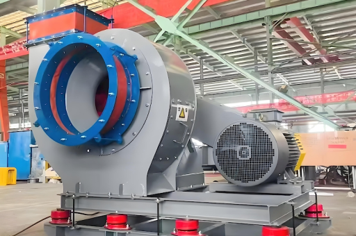
Installation
- Foundation: Use a concrete inertia base with vibration isolators. Ensure the base weight is at least 3 times the fan weight.
- Ductwork: Inlet and outlet ducts should be straight for at least 2–3 diameters to avoid flow distortion. Use expansion joints to prevent thermal stress transmission.
- Electrical: Verify motor current draw at startup and full load. Install overload protection and soft starters if the motor is >75 kW.
Maintenance Schedule
- Weekly: Check vibration levels (bearing velocity < 6 mm/s RMS). Listen for unusual noise.
- Monthly: Inspect impeller for dust buildup or erosion. Clean with compressed air or soft brush.
- Quarterly: Grease bearings per manufacturer specifications (typically lithium-based grease, relubrication every 500–1000 operating hours).
- Annually: Perform full dynamic balancing. Replace seals and gaskets. Measure motor insulation resistance.
Common Troubleshooting Issues
| Problem | Possible Cause | Solution |
|---|---|---|
| High vibration | Impeller imbalance or bearing wear | Rebalance impeller; replace bearings |
| Motor overheating | Incorrect voltage or overload | Verify voltage; reduce system resistance |
| Low airflow | Blocked inlet or outlet | Check dampers, filters, and ductwork |
| Excessive noise | Resonance or blade stall | Add silencers; adjust operating point |
Frequently Asked Questions (FAQ)
Q1: What does the "9-26-10D" designation mean?
A: "9-26" refers to the high-pressure series and specific blade geometry. "10D" means the impeller diameter is 1000 mm (10 decimeters) and the fan is direct-driven (no belts). This is an industry-standard nomenclature, also used by manufacturers on platforms such as fan resources.
Q2: Can the 9-26-10D be used for high-temperature applications?
A: Yes, but material upgrades are required. For temperatures above 150°C, specify a stainless steel impeller and high-temperature bearings. For continuous operation at >250°C, consider a heat-resistant alloy with active cooling for the shaft and bearing housing.
Q3: How do I calculate the required power for a specific application?
A: Use the formula:
Power (kW) = (Airflow in m³/s × Total Pressure in Pa) / (1000 × Fan Efficiency × Drive Efficiency)
For the 9-26-10D, typical fan efficiency is 75–82%. Direct drive efficiency is roughly 0.98. Always add a 10–15% safety margin for motor sizing.
Q4: What is the typical lifespan of a 9-26-10D fan?
A: With proper maintenance (regular balancing, bearing replacement, and cleanliness), the mechanical lifespan exceeds 15 years. The motor may require rewinding or replacement after 10–12 years depending on operating conditions.
Q5: Is variable frequency drive (VFD) operation recommended?
A: Yes, VFDs are highly recommended for energy savings. However, avoid operating below 20% of rated speed—this can cause unstable flow and possible surge. Always consult the fan's critical speed map to avoid resonance zones.
Conclusion: Why the 9-26-10D is a Strategic Investment
The 9-26-10D High-Pressure Centrifugal Fan is a proven workhorse for industries that demand reliable performance under high backpressure. Its backward-curved blade design, direct drive efficiency, and robust construction translate into lower total cost of ownership over the long term. While the upfront investment may be higher than generic fans, the energy savings, reduced downtime, and extended service life yield an attractive ROI.
When evaluating suppliers, consider factors such as dynamic balancing quality, material certifications, and after-sales support. Reputable manufacturers listed on fan directories often provide customized performance curves and commissioning assistance.
Final recommendation: For any industrial system with a design pressure above 6000 Pa and continuous operation requirements, the 9-26-10D is likely the most cost-effective and technically sound choice on the market today. Invest in proper installation and a preventive maintenance program, and this fan will deliver decades of dependable service.