This article's table of contents introduction:

- What is an Induced Draft Fan?
- How It Works in a Heating Furnace
- Key Components of an ID Fan System
- Critical Design Considerations
- Why is it called "Draft"?
- Typical Problems & Troubleshooting
- Control Strategy
- Safety Note
Here is a detailed explanation of an Induced Draft (ID) Fan in the context of a heating furnace (commonly used in industrial boilers, power plants, steel reheat furnaces, or petrochemical heaters).
What is an Induced Draft Fan?
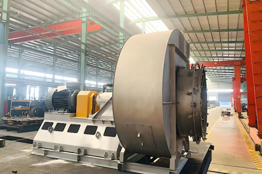
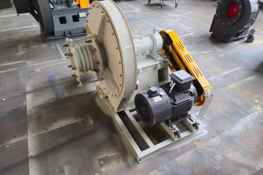
An Induced Draft Fan is a mechanical device located after the furnace (on the "cold" or "exit" side of the heat exchangers and dust collectors). Its primary purpose is to pull or suck the hot flue gases (the products of combustion) out of the furnace and through the system, creating a negative pressure (vacuum) inside the furnace.
Contrast with Forced Draft (FD) Fan: An FD fan pushes air into the furnace (positive pressure). An ID fan pulls air out of the furnace.
How It Works in a Heating Furnace
- Air Intake: Fresh air is brought into the furnace (usually by an FD fan or natural draft).
- Combustion: Fuel (gas, oil, coal, or biomass) burns, creating hot flue gases (CO2, H2O, N2, and particulates).
- Heat Exchange: The hot gases travel through the furnace chamber and heat exchanger tubes, transferring heat to the process (e.g., water to steam, or steel to temperature).
- Draft Creation: The ID fan, located at the end of the flue gas path (often after the baghouse or scrubber), creates a low-pressure area. This sucks the cooled gases through the system and out the chimney (stack).
- Negative Pressure: The critical result is that the furnace pressure is kept slightly negative (e.g., -0.5 to -2.0 inches of water column). This prevents dangerous hot gases from leaking out of the furnace casing into the boiler house.
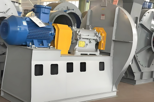
Key Components of an ID Fan System
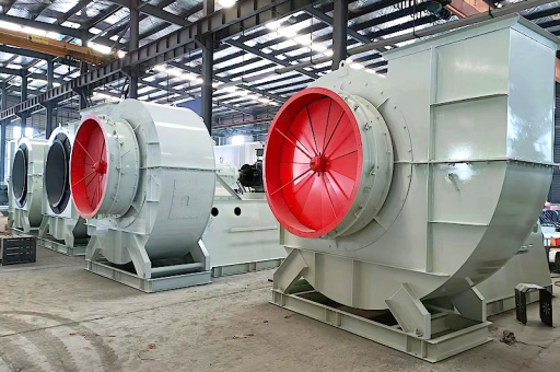
- Fan Wheel (Impeller): Typically a backward-curved or radial blade design. Backward-curved is more efficient, while radial is more robust for dirty gases.
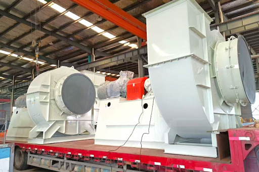
- Casing: A heavy-duty, usually spiral-shaped housing.
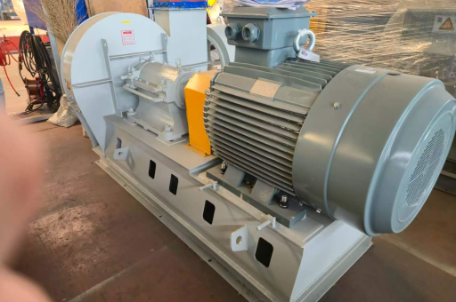
- Drive System: Motor, coupling (or V-belt), and bearings. Modern systems use a Variable Frequency Drive (VFD) for speed control.
- Dampers: Inlet vanes or outlet dampers to control airflow mechanically (if a VFD is not used).
- Shaft Seal: Seals the shaft where it passes through the casing to prevent air leaks into the low-pressure area.
Critical Design Considerations
ID fans face the most difficult operating conditions in a heating system:
- High Temperature: Flue gases can be 150°C – 400°C (300°F – 750°F). Fans often require:
- Water-cooled or oil-cooled bearings.
- High-temperature alloys (e.g., Corten, SS316) for the impeller.
- Shaft cooling fins or air cooling jackets.
- Abrasive Dust: Unburned fuel, fly ash, and soot erode the fan blades.
- Solution: Hard-faced blades (chrome carbide overlay), sacrificial liners, or "airfoil" blade designs.
- Corrosion: If fuel contains sulfur (H2S/SO2), condensation of acidic gases (sulfuric acid) can destroy the fan.
- Solution: Maintain flue gas temperature above the acid dew point or use corrosion-resistant coatings.
- Vibration: Due to fly ash build-up on the blades (unbalance).
- Solution: Bearing vibration sensors, wash systems (steam or water lances), and regular cleaning schedules.
Why is it called "Draft"?
The term "draft" refers to the pressure difference that causes airflow.
- Natural Draft: Relies on the stack (chimney) height. Hot air rises, creating a slight vacuum.
- Induced Draft: A fan is used to induce this flow artificially. It allows for:
- Smaller stacks (less chimney height required).
- Better control over combustion.
- Faster response to load changes.
Typical Problems & Troubleshooting
| Problem | Likely Cause | Solution |
|---|---|---|
| High Vibration | Fly ash build-up on blades (unbalance) | Clean impeller (steam/water wash) |
| Worn/eroded blades | Replace or weld repair blades | |
| Bearing failure | Replace bearings; check lubrication | |
| Low Flow/Head | Damper malfunction | Check actuator linkage |
| Dirty inlet screen/filter | Clean or replace filter | |
| Clogged flue gas path (heat exchanger) | Clean boiler tubes | |
| Overheating | High inlet gas temperature | Check upstream combustion settings |
| Cooling system failure (bearings) | Restore water/air cooling | |
| Motor Overload | Damper stuck open (high load) | Check damper control |
| High gas density (temperature too low) | Check furnace temperature |
Control Strategy
The ID fan is typically controlled by a Furnace Draft Controller:
- A Draft Transmitter measures the pressure inside the furnace.
- The controller compares this to a setpoint (e.g., -0.2" WC).
- If the draft is too high (too negative), the controller slows the fan (or closes the damper).
- If the draft is too low (approaching positive), the controller speeds up the fan to pull more gas.
Note: In most systems, the FD fan is controlled by air flow (to match the fuel flow), while the ID fan is controlled by furnace pressure to ensure safety.
Safety Note
Never start an ID fan if the furnace has accumulated combustible gases (e.g., after a flameout). The fan can pull air into the box, potentially causing an explosion. A proper purge cycle (running the fan for several minutes with no fuel) must always be performed first.