Article Title: The Critical Role of the 110kW High-Temperature Flue Gas Cooling Fan in Modern Industrial Emission Control Systems
Table of Contents
- Introduction: Why 110kW High-Temperature Flue Gas Cooling Fans Matter
- Technical Specifications: What Makes a 110kW Fan “High-Temperature”
- Core Design Features: Materials, Bearings, and Cooling Mechanisms
- Operational Principles: How the Fan Manages Extreme Heat and Particulate
- Application Case Studies: Power Plants, Cement Kilns, and Incinerators
- Selection & Sizing: Matching the 110kW Fan to Your System
- Installation & Maintenance Best Practices for Long Service Life
- Energy Efficiency & Variable Frequency Drive Integration
- Frequently Asked Questions (FAQ)
- Conclusion: Future Trends in High-Temperature Flue Gas Fan Technology
Introduction: Why 110kW High-Temperature Flue Gas Cooling Fans Matter
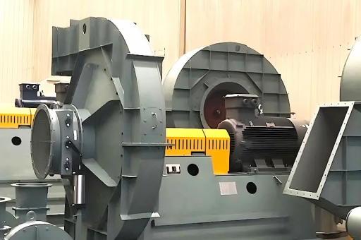
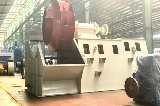
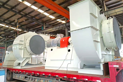
In the global push for cleaner industrial emissions, the 110kW high-temperature flue gas cooling fan has quietly become a backbone component in pollution control systems. These powerful centrifugal fans are specifically engineered to handle exhaust gases that exit combustion processes—such as those from coal-fired boilers, cement rotary kilns, or waste-to-energy incinerators—at temperatures ranging from 250°C to 650°C (482°F to 1202°F) .

Unlike standard ventilation fans, a 110kW-rated unit must endure not only extreme heat but also the corrosive effects of sulfur dioxide, nitrogen oxides, and particulate-laden gas streams. The 110kW power class is particularly popular because it provides an optimal balance between airflow capacity (typically 80,000 to 150,000 m³/h) and static pressure requirements (3,000 to 6,000 Pa) for medium-to-large industrial duct networks.
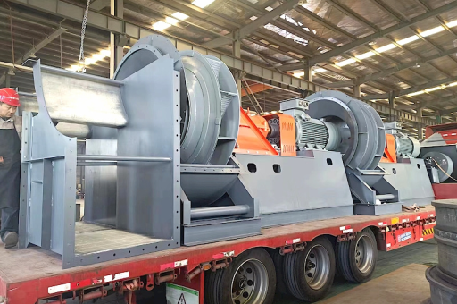
Why 110kW specifically? This power rating often represents the “sweet spot” where a single fan can serve a complete flue gas treatment train—including the cooling tower, baghouse filter, and scrubber—without requiring parallel fan banks. This reduces capital expenditure, floor space, and control complexity.
Technical Specifications: What Makes a 110kW Fan “High-Temperature”
A 110kW high-temperature flue gas cooling fan is not merely a standard fan with a bigger motor. It is a precision-engineered machine that meets strict performance criteria under continuous thermal stress.
Key Performance Parameters
| Parameter | Typical Range for 110kW Class |
|---|---|
| Rated Power | 110 kW (150 HP) |
| Maximum Gas Temperature | 250°C to 650°C (depending on material grade) |
| Airflow (Volume) | 80,000 – 150,000 m³/h |
| Total Pressure Rise | 3,000 – 6,000 Pa |
| Impeller Diameter | 1,200 – 2,000 mm |
| Rotational Speed | 980 – 1,480 RPM (direct drive); 600 – 900 RPM (belt drive) |
| Noise Level (1m) | 85 – 95 dB(A) with silencer |
Temperature Classifications
The industry classifies high-temperature fans into three tiers:
- Class 1 (250°C–350°C): Used in exhaust gas recirculation and mild preheater systems. The housing is typically carbon steel, with impeller made from Q345R or 16Mn steel.
- Class 2 (350°C–450°C): Common in cement preheaters and biomass gasifiers. Requires alloy steel (e.g., 15CrMoR) for both impeller and housing.
- Class 3 (450°C–650°C): Found in waste incinerators and glass furnace exhaust. Impeller blades are made from stainless steel 310S or Hastelloy X, and the shaft is internally cooled via a unique air or water jacket system.
A true 110kW high-temperature fan for flue gas cooling must be validated for continuous operation at the rated temperature without thermal deformation or excessive bearing wear.
Core Design Features: Materials, Bearings, and Cooling Mechanisms
The longevity of a 110kW high-temperature flue gas cooling fan depends heavily on three structural aspects: material selection, bearing system, and cooling integration.
1 Material Selection
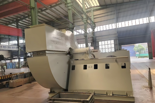
- Housing (Casing): For temperatures up to 400°C, a double-wall casing with air gap cooling is standard. The inner wall is often made from SA-516 Gr.70 or P265GH, while the outer skin remains cooler to prevent personnel injury.
- Impeller (Rotor): At 400°C+, blades are typically backward-curved airfoil design made from S31008 (310S) stainless steel, which maintains tensile strength up to 850°C. For extreme corrosion, nickel-chromium alloys like Inconel 625 are used—though at significantly higher cost.
- Shaft: For Class 3 applications, the shaft is often hollow and pipe-cooled. The material is typically 42CrMo4 with heat treatment for fatigue resistance.
2 Bearing Assembly
The bearings are the most vulnerable component. Standard grease-packed bearings fail above 100°C, so all 110kW high-temperature fans use:
- Outboard pedestal bearings with insulated housings to reduce heat transfer.
- Oil bath or circulating oil lubrication systems with oil coolers. The oil outlet temperature must remain below 75°C.
- Thermocouple sensors integrated into the bearing housing for continuous monitoring. A typical alarm threshold is 85°C, with automatic shutdown at 95°C.
3 Cooling Mechanisms
There are two primary cooling strategies:
- Direct Air Cooling: A secondary cooling fan (often 2–5 kW) mounted on the fan shaft blows ambient air over the shaft between the housing and bearing. This is effective up to 400°C.
- Water Jacket Cooling: For 450°C+, a closed-loop water jacket surrounds the shaft seal area. The cooling water flow rate is typically 5–10 L/min, with a maximum outlet temperature of 45°C to prevent scaling.
Expert Tip: Many facilities overlook the cooling fan or water circulation pump, leading to premature bearing failure. Always specify a redundant pump for water-jacketed systems.
Operational Principles: How the Fan Manages Extreme Heat and Particulate
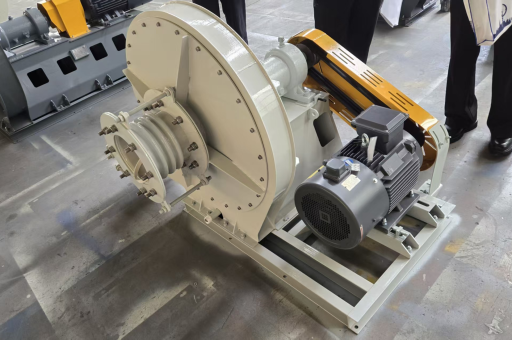
The 110kW fan operates under the centrifugal principle: gas enters axially, is accelerated by the rotating impeller, and exits radially into a volute casing. However, because it handles hot, dirty gas, several unique design adaptations are required.
1 Thermal Expansion Accommodation
The rotor and casing expand at different rates. To prevent binding:
- The impeller is mounted at the cold end of the shaft (closer to the motor or belt drive).
- An axial expansion joint is installed between the fan inlet and ductwork.
- Radial clearances between the impeller tip and casing are increased by 2–4 mm compared to a cold fan.
2 Erosion Control
Flue gas often contains fly ash and unburned carbon particles. The fan's internal surfaces are lined with:
- Ceramic tile or hard-facing weld overlay on the leading edge of blades.
- Replaceable wear plates in the volute at the 6 o’clock and 9 o’clock positions (where particle impact is highest).
A typical 110kW fan for a cement preheater will need impeller reblading every 18–24 months, depending on dust loading.
3 Dynamic Balancing
Because the shaft and impeller experience significant thermal gradients, the fan must be balanced at operating temperature, not at cold state. On-site trim balancing is often required after initial 100 hours of operation. Vibration velocity should not exceed 5 mm/s (RMS) according to ISO 14694.
Application Case Studies: Power Plants, Cement Kilns, and Incinerators
1 Coal-Fired Power Plant (500 MW Boiler)
A 110kW forced-draft flue gas cooling fan was installed downstream of the economizer to lower the exhaust temperature from 380°C to 180°C before entering the electrostatic precipitator. The fan delivered 120,000 m³/h at 4,500 Pa. After 3 years of operation, the bearing system required only one oil change per 6 months, and the impeller showed minimal erosion thanks to ceramic tile coating.
2 Cement Kiln Preheater Tower
In a 5,000 tpd cement plant, a 110kW high-temperature fan was used for the conditioning tower exhaust. Gas temperature fluctuated between 320°C and 480°C due to raw meal feed variations. The fan was equipped with variable frequency drive (VFD) and a water spray injection system to protect the motor. The maintenance interval was extended from 12 to 24 months by switching from grease to oil mist lubrication.
3 Municipal Solid Waste Incinerator
A waste-to-energy plant required a 110kW fan to handle gases containing HCl, SO₂, and dioxins at 650°C. The fan was fabricated entirely from 310S stainless steel with a double-wall water-cooled housing. The cooling water system included a plate heat exchanger to recover waste heat. The fan achieved a 15-year service life with major overhauls every 4 years.
Selection & Sizing: Matching the 110kW Fan to Your System
When selecting a 110kW high-temperature flue gas cooling fan, use the following checklist:
- Gas Temperature Profile: Obtain the maximum, minimum, and average temperatures. Most fans are rated for continuous operation at a single “hot point.” Do not assume a 400°C fan can run briefly at 450°C—material creep increases exponentially.
- Gas Composition: Test for chlorine, sulfur, and moisture content. Chlorine above 50 ppm requires nickel alloy impellers.
- System Resistance: Measure the pressure drop across all downstream equipment (scrubbers, baghouses, ducts). The fan must overcome this at minimum flow.
- Density Correction: Fan performance curves are typically based on standard air (1.2 kg/m³ at 20°C). At 400°C, air density drops to ~0.5 kg/m³, so the power required is lower, but the volume flow and pressure capacity must be corrected accordingly.
Example Calculation: A 110kW fan moving 100,000 m³/h at 400°C will consume only about 65 kW of motor power because of reduced gas density. This means the motor can be downsized or the fan can operate at reduced speed.
Installation & Maintenance Best Practices for Long Service Life
1 Installation
- Foundation: Mount on a concrete inertia block with vibration isolators. A 110kW fan weighs 3–5 tons, so the foundation mass should be at least 3x the fan weight.
- Ductwork: Use flexible connectors at both inlet and outlet to absorb thermal expansion.
- Drainage: Install a condensate drain at the lowest point of the volute to remove acid condensation during start-up.
2 Maintenance Schedule
| Interval | Activity |
|---|---|
| Daily | Check vibration (via online sensors). Note bearing temperature. |
| Weekly | Inspect oil level and color. Look for metal flakes. |
| Monthly | Clean cooling water strainer. Check belt tension (if applicable). |
| Quarterly | Perform thermographic scan of motor and bearings. |
| Annually | Replace oil and filter. Inspect impeller for cracking or wear. |
| 2-3 Years | Rebalance rotor at operating temperature. |
Energy Efficiency & Variable Frequency Drive Integration
A 110kW fan running continuously at full speed is a major energy consumer. However, flue gas flow requirements rarely remain constant. By integrating a variable frequency drive (VFD) , power savings of 25–40% are typical.
For example, a cement plant operating the fan at 80% speed reduces power consumption to 51.2 kW (since power is proportional to the cube of speed). Over 8,000 hours/year, this saves approximately 470,000 kWh—equivalent to €40,000–€50,000 in electricity costs.
VFD Selection Criteria:
- Use a 6-pulse or 12-pulse VFD with input reactor to handle voltage distortion.
- Install a brake resistor or regenerative unit if the fan must decelerate quickly.
- Enable PID control with pressure or temperature feedback to protect the fan from surging.
Frequently Asked Questions (FAQ)
Q1: Can a 110kW standard fan be used for high-temperature flue gas?
No. A standard fan uses carbon steel impellers and grease-packed bearings that will fail within weeks at 200°C+. Only a properly engineered high-temperature fan with alloy steel, cooling jackets, and heat-resistant lubrication is suitable.
Q2: How often should I replace the impeller of a 110kW high-temperature fan?
Typically every 3–5 years, depending on gas abrasiveness. If ceramic coating is used and the filter upstream is efficient, 5–7 years is achievable.
Q3: What is the maximum temperature a 110kW fan can handle?
With standard alloy steel, 450°C continuous. With 310S or Hastelloy, 650°C. For short-term peaks up to 750°C, advanced ceramic-lined designs exist but are very costly.
Q4: Is water jacket cooling mandatory?
Only for gases above 450°C. Below that, forced air cooling is adequate and simpler to maintain.
Q5: What causes premature bearing failure in these fans?
Three main causes: (1) Inadequate cooling water flow, (2) misalignment between motor and fan, and (3) thermal expansion of the shaft not being absorbed by the bearing mounting system.
Q6: Can I use a belt drive for a 110kW high-temperature fan?
Yes, but only for moderate temperatures (up to 300°C). For higher temperatures, direct drive is preferred because belts degrade in hot environments and can slip.
Q7: How do I calculate the actual power required for my flue gas parameters?
Use the formula:
( P = \frac{Q \times \Delta p}{\eta \times 1000} )
Where ( Q ) is volume flow (m³/s), ( \Delta p ) is pressure rise (Pa), and ( \eta ) is fan efficiency (typically 0.75–0.85). Then correct for gas density and temperature.
Conclusion: Future Trends in High-Temperature Flue Gas Fan Technology
The 110kW high-temperature flue gas cooling fan is a mature yet evolving technology. Key developments on the horizon include:
- Additive-manufactured impellers made from cobalt-chrome alloys that resist both heat and erosion better than castings.
- Smart sensors with IoT connectivity that predict bearing life and detect impeller imbalance before failure.
- Integrated heat recovery where the fan’s oil or water cooling loop preheats feedwater for the boiler, improving overall plant efficiency by 1–2%.
As global emission standards become stricter, industries such as cement, steel, and waste-to-energy will continue to demand reliable, energy-efficient 110kW fans that can operate with minimal downtime. Investing in a properly engineered fan—with correct material selection, cooling design, and maintenance planning—is not a cost but a strategic asset for any facility that must move hot, dirty gas safely and efficiently.