This article's table of contents introduction:

- The Problem: Why an ID Fan needs a Special Seal
- The Solution: The Magnetic Fluid Seal
- Application in an Induced Draft Fan: The Hybrid Design
- Layout Diagram (Simplified)
- Key Advantages for ID Fan Applications
- Critical Considerations & Challenges
- Manufacturers & Where to Find Them
- Is it the Right Choice?
This is a specific and advanced engineering application. A Magnetic Fluid Seal (MFS) , also known as a Ferrofluidic Seal, used in an Induced Draft (ID) Fan is a solution designed to solve a very difficult problem: zero-leakage sealing of a high-speed rotating shaft in a large, often harsh, industrial environment.
Here is a detailed breakdown of how this works, why it's used, and its key characteristics.
The Problem: Why an ID Fan needs a Special Seal
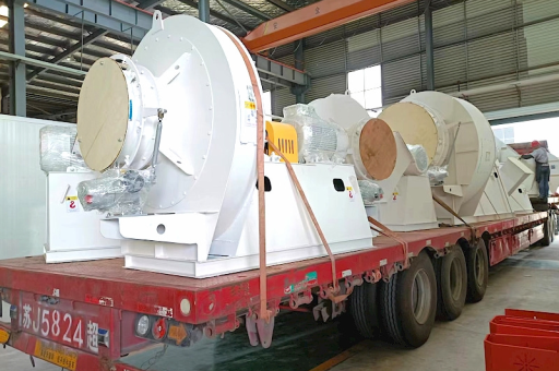
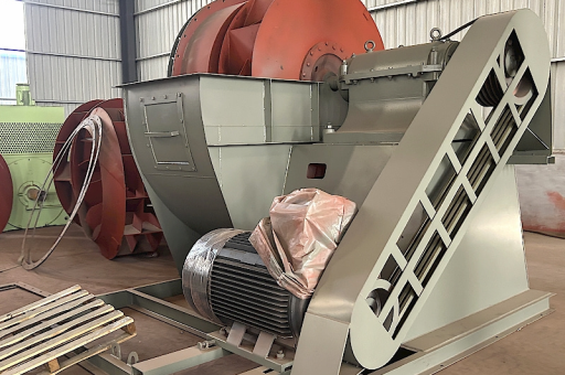
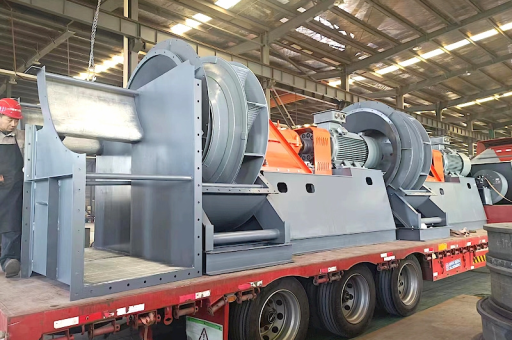
An Induced Draft Fan is a large fan located at the "back end" of a boiler or furnace system (e.g., in a power plant or industrial incinerator). Its job is to pull hot combustion gases through the system and up the chimney.
The sealing challenge is severe:
- Negative Pressure: The fan is under vacuum (suction), which can actively pull ambient air into the system (leaks in).
- Hot, Dirty, Corrosive Gases: The "air" being moved is flue gas containing fly ash, sulfur oxides (SOx), and moisture. This mixture is abrasive and corrosive.
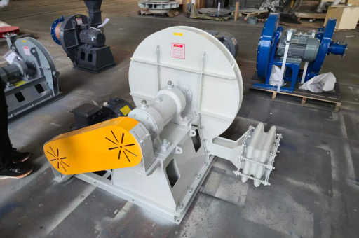
- Large Shaft: The fan shaft is large (several inches in diameter) and rotates at moderate to high RPM (e.g., 900-1500 RPM).
- Shaft Runout & Vibration: Large industrial fans are heavy and can have significant mechanical vibration and shaft deflection.
Traditional seals (labyrinth seals, carbon rings, or stuffing boxes) fail due to wear, leakage, and inability to handle the vacuum.
The Solution: The Magnetic Fluid Seal
A magnetic fluid seal creates a perfect, zero-leakage barrier using a stabilized colloidal liquid.
The Key Components:
- Magnetic Fluid (Ferrofluid): A stable suspension of nanometer-sized ferromagnetic particles (magnetite) in a carrier fluid (like synthetic oil or a low vapor pressure fluorinated fluid). This fluid is non-toxic and designed for the specific operating conditions.
- Permanent Magnet: A powerful, high-energy magnet (usually Neodymium-Boron or Samarium-Cobalt).
- Pole Blocks (Focusing Rings): Soft iron rings with sharp, closely-spaced teeth. These concentrate the magnetic field.
- Shaft Sleeve: A non-magnetic or magnetically permeable sleeve mounted on the rotating shaft.
How It Works:
- The magnet and pole blocks are mounted in the stationary housing.
- A small gap (typically 0.1 - 0.3 mm) exists between the pole block teeth and the rotating shaft sleeve.
- The magnetic field crosses this gap. A few milliliters of ferrofluid are injected into the gap.
- The magnetic field instantly traps the fluid, holding it in place between the teeth and the shaft, forming a series of "liquid O-rings" (stages). Each stage can withstand a specific differential pressure (typically 1-3 PSI per stage, depending on design).
- The stationary fluid creates a perfect, compliant, zero-leakage seal with zero friction.
Application in an Induced Draft Fan: The Hybrid Design
A standard MFS cannot handle the extreme pressure differentials (e.g., 20-30 PSI) of a general pump. For an ID fan, the pressure differential is much smaller (often just a few PSI of vacuum), but the environmental threats are huge.
Therefore, the application is almost always a Hybrid Protection System:
- Primary Threat - Particulate & Corrosion: The first line of defense is not the MFS, but Purge Gas (Buffer Air) . Clean, dry, instrument air or nitrogen is injected into a cavity in front of the MFS. This positive pressure (higher than the process vacuum) pushes dirty flue gas away from the seal.
- Buffer Zone: The purge gas creates a clean, inert atmosphere in the seal chamber.
- Secondary Seal - The MFS: The magnetic fluid seal acts as the final, zero-leakage barrier. It seals against the purge gas on one side and the atmosphere on the other. This is a much cleaner, more manageable environment for the ferrofluid.
- Backup (Optional): A simple carbon face seal or lip seal might be placed after the MFS as a dry backup, or the MFS itself is designed as the only dynamic seal.
Layout Diagram (Simplified)
[ATMOSPHERE / DRIVE SIDE]
      |
[Backup Seal (Optional)]
      |
[MFS - Ferrofluid Barrier]  <--- ZERO LEAKAGE SEAL
      |
[Buffer Chamber]            <--- Clean, dry buffer air in.
      |
[Buffer Seal (Bearing Isolator / Labyrinth)]  <--- Reduces flow of dirty gas into buffer chamber.
      |
[FLUE GAS SIDE (Vacuum)]
Key Advantages for ID Fan Applications
| Feature | Benefit for ID Fan |
|---|---|
| Zero Leakage | No air ingress into the flue gas stream (improves combustion efficiency, prevents corrosion in cold-end ducts). No flue gas leakage to atmosphere (critical for emissions & safety). |
| Zero Wear & Long Life | No contact. No particles, no dust from a wearing seal. Life of 5-10+ years is common. |
| Handles Vibration & Runout | The liquid seal is compliant and self-centering. It can accommodate significant shaft deflection without failing (unlike carbon rings). |
| Low Power Consumption | No friction means near-zero parasitic drag on the motor. |
| Low Maintenance | The seal is a "fit-and-forget" component. The only maintenance is occasional monitoring of buffer gas pressure and flow. |
| Compatibility | The carrier fluid can be chosen to be inert to SOx, moisture, and high temperatures (within limits, usually <80°C / 175°F at the seal face, due to buffer cooling). |
Critical Considerations & Challenges
- Temperature Management: The ferrofluid itself has a temperature limit (typically < 80°C). If the fan shaft conducts heat from the hot flue gas, a cooling system (water jacket or air cooling) must be integrated into the stationary housing.
- Cost: A hybrid MFS system is significantly more expensive than a standard labyrinth or carbon ring seal. It is justified by long-term reliability, zero leakage, and reduced maintenance.
- Buffer Gas Requirement: The system must have a reliable, clean, dry supply of buffer air or nitrogen. Loss of buffer gas will quickly lead to contamination of the ferrofluid with ash and subsequent failure.
- Shaft Surface Finish: The shaft sleeve must have a very fine surface finish (typically 8-16 micro-inches Ra) and be made of a high-quality, wear-resistant material.
- Process Upsets: If the fan sees a pressure surge that exceeds the MFS's burst pressure (e.g., a sudden slug of condensate creating a high pressure spike), the seal can blow out. It will reform automatically when pressure normalizes, but it requires re-injection of ferrofluid.
Manufacturers & Where to Find Them
- Ferrotec (USA/Japan): The dominant global leader in ferrofluid technology and engineered seal systems.
- Eagle Industry / EagleBurgmann (Japan/Germany): Offer hybrid MFS systems for industrial fans.
- Fluiten (Italy): Specialize in zero-leakage seals for high-speed rotating equipment.
- MW Components / Autocam Medical (formerly MFS Technology): Smaller, specialized providers.
Is it the Right Choice?
Magnetic fluid seals are the best choice for an ID fan when:
- Zero leakage is mandatory (emissions regulations, process contamination concerns).
- Shaft vibration is severe (causing premature failure of mechanical seals).
- High reliability and low maintenance are worth a higher upfront cost.
- A clean, reliable buffer gas source is available.
They are NOT the best choice when:
- The fan operates at very high temperatures (>150°C / 300°F at the seal face without cooling).
- The budget is constrained.
- A simple, low-cost labyrinth seal with acceptable leakage is permitted.
In summary: A magnetic fluid seal for an induced draft fan is a high-performance, zero-leakage, long-life solution that solves the problems of dust, vacuum, and vibration. It is not a simple replacement for a packing gland; it is a complete engineered system that requires a buffer gas supply and is appropriate for critical applications where downtime is expensive.