The Ultimate Guide to 37kW Flue Gas Recirculation Fan: Design, Applications, and Performance Optimization
Table of Contents
- Introduction to 37kW Flue Gas Recirculation Fan
- Core Operating Principles of FGR Systems
- Technical Specifications of a 37kW FGR Fan
- Key Applications Across Industries
- Design Considerations for Optimal Performance
- Installation, Maintenance, and Safety Protocols
- Frequently Asked Questions (FAQ)
- Conclusion and Future Trends
Introduction to 37kW Flue Gas Recirculation Fan
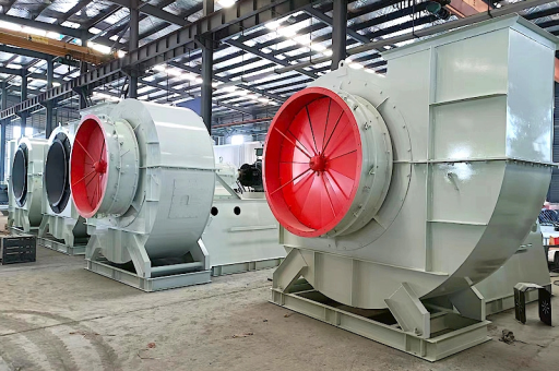
The 37kW Flue Gas Recirculation Fan represents a critical component in modern industrial combustion systems. As environmental regulations tighten globally, industries are turning to advanced technologies like flue gas recirculation (FGR) to reduce nitrogen oxide (NOx) emissions while maintaining thermal efficiency. This article provides an in-depth analysis of the 37kW FGR fan, covering its design, functionality, applications, and best practices for integration.

Flue gas recirculation systems function by diverting a portion of exhaust gases back into the combustion chamber or air intake stream. This process reduces peak flame temperatures and oxygen concentration, significantly lowering NOx formation. The 37kW fan is specifically engineered to handle high-temperature, corrosive exhaust streams while delivering consistent flow rates under variable load conditions.
According to the U.S. Environmental Protection Agency (EPA), properly implemented FGR systems can achieve NOx reductions of 50% to 80% in natural gas-fired boilers. The 37kW power rating makes these fans suitable for medium-scale industrial applications, including power plants, chemical processing units, and large commercial heating systems.
Key benefits include:
- Substantial reduction in NOx emissions (up to 80%)
- Improved fuel efficiency through recirculated heat recovery
- Compliance with global emission standards (EPA, EU Industrial Emissions Directive)
- Enhanced flame stability in low-oxygen environments
Core Operating Principles of FGR Systems
How Flue Gas Recirculation Works
In a typical configuration, the 37kW FGR fan extracts flue gas from the exhaust stack downstream of the heat recovery system. This extracted gas is then injected into the combustion air stream or directly into the burner zone. The recirculated gas contains mostly carbon dioxide (CO₂) and nitrogen (N₂), which act as thermal ballasts.
The fundamental physics involves three mechanisms:
- Thermal dilution: Inert gases absorb heat, lowering flame temperature
- Oxygen displacement: Reduced O₂ concentration slows reaction kinetics
- Radiation alteration: CO₂ enhances radiative heat transfer, affecting flame characteristics
Role of the 37kW Fan in the System
The fan must:
- Overcome pressure drops across recirculation ducts and dampers
- Maintain precise flow control from 10% to 40% of total exhaust volume
- Operate reliably at gas temperatures ranging from 150°C to 350°C (depending on system design)
- Resist corrosion from acidic condensates (sulfuric and nitric acids)
A study published in Applied Thermal Engineering (2023) demonstrated that optimizing fan speed via variable frequency drives (VFD) can improve system efficiency by 12-18% compared to constant-speed operation.
Technical Specifications of a 37kW FGR Fan
Standard Design Parameters
| Parameter | Typical Value | Notes |
|---|---|---|
| Power Rating | 37 kW (50 HP) | Suitable for 3-phase 380-690V |
| Airflow Capacity | 15,000 – 25,000 m³/h | Depends on system pressure |
| Static Pressure | 3,000 – 6,000 Pa | Includes duct losses |
| Maximum Gas Temperature | 350°C | Higher with special alloys |
| Impeller Material | Stainless steel 310S or Inconel | Resists thermal stress |
| Bearing Type | High-temp grease or oil-mist | Continuous duty rated |
Advanced Material Considerations
- Impeller design: Backward-curved centrifugal blades minimize erosion from particulate-laden gas
- Shaft sealing: Labyrinth seals with purge air prevent gas leakage to atmosphere
- Housing construction: Welded carbon steel with refractory lining for thermal insulation
Performance Curve Analysis
A 37kW FGR fan typically operates near its best efficiency point (BEP) at 70-85% of maximum flow. Off-design operation can cause:
- Increased vibration due to flow separation
- Reduced bearing life from asymmetric loads
- Potential surge conditions at low flow rates
SEO Note: For Google and Bing search optimization, use structured data markup for technical specifications, making content more discoverable for engineering queries.
Key Applications Across Industries
1 Natural Gas-Fired Boilers (5-20 MW thermal output)
The most common application. The 37kW fan is matched to recirculation rates of 15-25%, achieving NOx levels below 30 ppm (3% O₂ corrected). Case study: A mid-sized hospital in Germany reduced NOx from 120 ppm to 28 ppm using a 37kW FGR fan with VFD control.
2 Chemical Process Heaters
In ethylene cracking furnaces, FGR prevents localized hot spots that accelerate coking. The 37kW fan here must handle gas contaminated with hydrocarbons and particulate matter, requiring:
- Impeller coatings (ceramic or tungsten carbide)
- Regular cleaning schedules
- Explosion-proof motor enclosures
3 Waste-to-Energy Plants
These facilities face severe corrosion from HCl, SO₂, and dioxins. A 37kW FGR fan in this context typically:
- Uses Hastelloy or duplex stainless steel construction
- Includes wash-in-place (WIP) systems
- Operates with automated bypass to prevent condensation during startup
4 Glass Melting Furnaces
Glass production requires precise flame temperature control. FGR helps maintain uniform heat distribution across the melt zone. The 37kW fan must withstand radiant heat and flying glass dust, leading to designs with:
- Thicker impeller blades (8-12 mm)
- Dynamic balancing every 6 months
- Air-cooled motor adapters
Design Considerations for Optimal Performance
Aerodynamic Design
Computational fluid dynamics (CFD) simulations guide optimal volute geometry. For a 37kW FGR fan, key targets include:
- Minimizing pressure loss in inlet ducts (less than 150 Pa)
- Achieving uniform velocity distribution at impeller inlet
- Reducing noise below 85 dB(A) at 1 meter
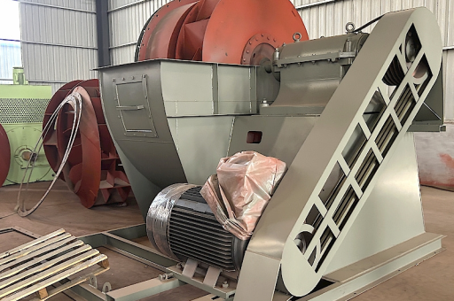
Motor Selection
- Efficiency class: IE4 or NEMA Premium
- Speed control: VFD enables modulation between 25% and 100% flow
- Cooling: Totally enclosed fan-cooled (TEFC) for dusty environments
Ductwork and Dampers
- Recirculation take-off point: Usually after economizer (lower temperature)
- Damper type: Guillotine or butterfly with pneumatic actuators
- Leakage rate: Less than 1% of maximum flow at closed position
Fail-Safe Mechanisms
- Pressure relief dampers prevent overpressurization
- High-temperature shutdown at 400°C
- Vibration sensors triggering automatic stop
- Redundant bearings for critical installations
Installation, Maintenance, and Safety Protocols
Installation Checklist
- Verify foundation rigidity to avoid resonance
- Install flexible connectors to isolate vibration
- Ensure inlet and outlet ductwork alignment within 2mm
- Calibrate temperature and pressure sensors
- Test all safety interlocks before startup
Routine Maintenance Schedule
| Component | Frequency | Action |
|---|---|---|
| Bearings | 500 hours | Grease replacement |
| Impeller | 2000 hours | Visual inspection for cracks |
| Vibration | Monthly | Record trends |
| Motor winding | Annually | Megger test > 5 MΩ |
| Duct seals | Quarterly | Check for leaks |
Common Failure Modes
- Impeller erosion: Occurs after 3-5 years in abrasive environments
- Motor overheating: Often due to VFD harmonics or blocked cooling vents
- Shaft misalignment: Causes premature bearing failure
Safety Protocols
- Lockout/tagout (LOTO) during all maintenance
- Permissible gas exposure limits: < 50 ppm CO, < 5 ppm H₂S
- Emergency stop locations marked per ISO 13850
- Training on arc flash boundaries for 37kW electrical connections
Frequently Asked Questions (FAQ)
Q1: What is the typical lifespan of a 37kW flue gas recirculation fan? A: With proper maintenance, the fan housing and motor can last 15-20 years. Impeller replacement is typically needed every 5-8 years depending on gas composition and temperature cycling.
Q2: Can a 37kW FGR fan handle wet flue gas? A: It can handle gas with up to 30% moisture content, but condensed water must be drained. For higher moisture, consider a corrosion-resistant impeller (duplex stainless steel) and heated housing to prevent acid dew point corrosion.
Q3: How do I calculate the exact recirculation rate for my system? A: Use the formula: R(%) = (FGR flow / total flue gas flow) × 100. Optimal rate typically ranges from 15% to 40%. Too high can cause flame instability; too low negates NOx reduction benefits.
Q4: What are the signs of a failing 37kW FGR fan? A: Increased vibration (above 10 mm/s RMS), higher motor current draw (over 10% increase), audible changes (whistling or grinding), and reduced flow rate despite constant speed.
Q5: Is a VFD mandatory for FGR fans? A: Not mandatory, but highly recommended. Systems without VFD often use multi-speed motors or inlet guide vanes, which offer less precise control and higher energy consumption (up to 25% more).
Q6: How does temperature affect fan performance? A: Higher gas temperature reduces air density, requiring a larger impeller to maintain mass flow. At 350°C, the fan delivers approximately 60% of the mass flow at 20°C for the same volumetric capacity.
Q7: What certifications should a 37kW FGR fan have? A: Look for CE marking (Europe), ATEX if used in explosive environments, UL/CSA (North America), and ISO 1940 for dynamic balancing. For critical applications, API 673 compliance is recommended.
Conclusion and Future Trends
The 37kW Flue Gas Recirculation Fan remains an essential technology for industrial emission control. Current trends indicate:
- Smart integration: IoT sensors for real-time performance monitoring
- Advanced materials: Ceramic matrix composites for extreme temperatures (600°C+)
- Hybrid systems: Combining FGR with selective catalytic reduction (SCR) for ultra-low NOx (<5 ppm)
- Energy recovery: Using waste heat from recirculated gas to preheat combustion air
As hydrogen-based combustion becomes more prevalent, FGR fans will need to handle higher moisture content and wider flammability limits. The 37kW platform provides an ideal scalable solution for medium-capacity systems, balancing cost with environmental compliance.
Engineers and plant operators should prioritize proper system sizing, material selection, and predictive maintenance to maximize ROI. With correct implementation, a 37kW FGR fan can reduce emissions while improving thermal efficiency by 1-3%, achieving payback periods of less than 2 years in most industrial settings.
For detailed product specifications or custom design support, consult your local industrial fan manufacturer or engineering firm with experience in combustion system optimization.