This article's table of contents introduction:

- The Critical Role of the Fan in Alumina Calcination
- Why "High-Efficiency" is Non-Negotiable
- Optimal Fan Configuration for Alumina Calcining
- Common Failure Modes & Troubleshooting
- Recommended Performance Monitoring
- Key Takeaway for Your Operation
This is a professional and specific query related to industrial thermal processing and mechanical equipment. To provide a helpful response, I will break down the purpose, selection criteria, critical benefits, and potential failure modes for a high-efficiency centrifugal fan in an alumina calcining furnace context.
The Critical Role of the Fan in Alumina Calcination
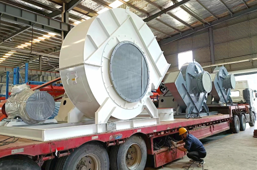
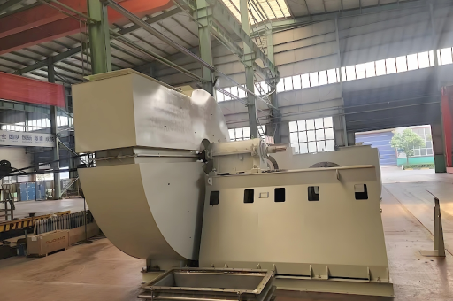
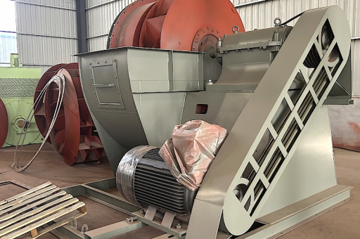
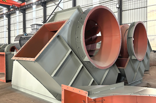
In a calcining furnace (e.g., a Gas Suspension Calciner or Rotary Kiln), the centrifugal fan is not just for general ventilation. It is a process-critical component for:
- Combustion Air Supply: Providing primary and secondary air to burn natural gas or fuel oil to reach ~1000-1100°C.
- Fluidization: In Fluidized Bed Calciners (e.g., "Flux" type), the fan maintains the "fountain" of alumina hydrate particles.
- Induced Draft (ID): Removing hot flue gases and fine dust from the kiln or cooler.
- Material Transport: Conveying alumina powder through cyclones and ducts.
Why "High-Efficiency" is Non-Negotiable
Standard fans would fail in this environment. The high-efficiency design is required for:
| Requirement | Why Standard Fan Fails | High-Efficiency Solution |
|---|---|---|
| Temperature | Standard bearings/motor cook. | High-temp shaft seals + cooling fins or water-cooled bearings. Impeller made of Heat Resistant Steel (e.g., 16Mo3 or Hastelloy) for 400°C+ service. |
| Abrasion | Alumina (Al₂O₃, Mohs hardness 9) is extremely abrasive. Standard steel impellers erode in days. | Hardfacing on blade leading edges (e.g., Stellite or Inconel weld overlay) or ceramic-lined volute and impeller (alumina or silicon nitride tiles). |
| Dust Loading | Fine dust causes imbalance and vibration. | Backward-curved (BC) blades (non-clogging) with a robust dust extraction port on the volute bottom. |
| Variable Speed | Fixed flow leads to inefficiency at turndown. | VFD (Variable Frequency Drive) control to match calciner load, reducing power consumption by 20-40% compared to throttle control. |
| Efficiency Plateau | Peak efficiency is narrow. | Aerodynamically profiled blades (e.g., airfoil design) achieve >85% static efficiency across a wider flow range. |
Optimal Fan Configuration for Alumina Calcining
If you are specifying or procuring this fan, the ideal configuration is:
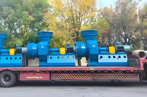
- Type: Single-width, double-width, or double-inlet (depending on flow demand).
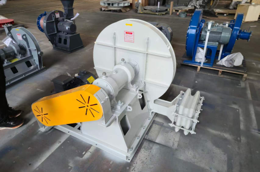
- Impeller Design: Backward-curved (BC) or Backward-inclined (BI) . Avoid radial blade or paddle fans (they are too abrasive and self-clogging).
- Drive: Direct drive (for high RPM) or belt drive (for tuning). VFD is essential.
- Material:
- Impeller: Stainless Steel 310S (for high temp) or Abrasion-Resistant Steel (e.g., Hardox 500) with ceramic coating.
- Shaft: Chrome-moly steel (e.g., 4140) with hardened sleeves at seals.
- Seals: Labyrinth or carbon ring seals to prevent dust ingress into bearings.
- Dampers: Inlet guide vanes (IGV) for pre-rotation control (added efficiency layer, used in combination with VFD for very large fans).
Common Failure Modes & Troubleshooting
Even with a high-efficiency unit, these issues are common:
- Mass Imbalance (Vibration):
- Cause: Alumina build-up on blades or erosion.
- Solution: Schedule compulsory cleaning (compressed air or water wash) every 3-6 months. Use vibration sensors (e.g., model: ePro MMS 6210) to trigger cleaning.
- Bearing Overheating:
- Cause: High ambient temperature (400°C+ air leaking from duct) + thermal soak from shaft.
- Solution: Upgrade to oil-mist lubrication or a cooling fan on the shaft. Verify alignment.
- Erosion Scoring on Volute:
- Cause: Fine alumina particles acting as sandpaper.
- Solution: Apply ceramic epoxy lining (e.g., Belzona 1811 or Devcon Ceramic Putty) to the cut-off point and volute tongue.
- Shaft Seal Failure:
- Cause: Dust ingress past the seal.
- Solution: Install a purge air system (clean, dry air at +0.5 bar) into the seal cavity to block dust.
Recommended Performance Monitoring
To ensure the "high-efficiency" claim is realized, install:
- Flowmeter: Probe-type or Annubar in duct (to measure m³/hr).
- Differential Pressure Transmitter: Across fan (to monitor static pressure).
- Vibration Probes: Two per bearing (horizontal + vertical).
- Motor Power Analyzer: Real-time kW reading to display specific power consumption (kWh per ton of alumina calcined).
Key Takeaway for Your Operation
If you are retrofitting an existing furnace: Ensure the new fan's inlet and outlet flange orientations match your existing ductwork. If you are designing a new furnace: The fan should be upstream of the main heat source (forced draft) or downstream (induced draft with high-temp rating). The VFD and Ceramic Coating are the two highest-ROI upgrades for this application.