This article's table of contents introduction:

- Table of Contents
- Introduction: What Is a Single Inlet Coupling Driven Induced Draft Boiler Fan?
- Core Mechanical Architecture and Working Principle
- Key Advantages Over Traditional Fan Configurations
- Critical Performance Metrics and Calculation Example
- Installation Best Practices and Common Pitfalls
- Maintenance, Vibration Analysis, and Troubleshooting
- Frequently Asked Questions (FAQ)
- Conclusion: Future Trends and Industry Relevance
** The Comprehensive Guide to Single Inlet Coupling Driven Induced Draft Boiler Fans: Design, Operation, and Optimization
Table of Contents
- Introduction: What Is a Single Inlet Coupling Driven Induced Draft Boiler Fan?
- Core Mechanical Architecture and Working Principle
- Key Advantages Over Traditional Fan Configurations
- Critical Performance Metrics and Calculation Example
- Installation Best Practices and Common Pitfalls
- Maintenance, Vibration Analysis, and Troubleshooting
- Frequently Asked Questions (FAQ)
- Conclusion: Future Trends and Industry Relevance
Introduction: What Is a Single Inlet Coupling Driven Induced Draft Boiler Fan?
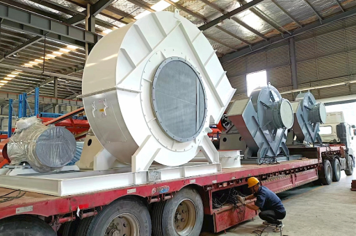
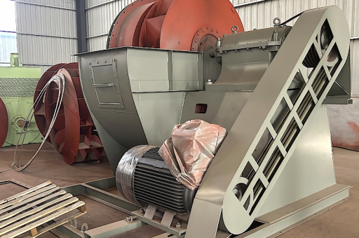
A Single Inlet Coupling Driven Induced Draft Boiler Fan is a specialized industrial fan used in steam boilers, thermal power plants, and large heating systems. Its primary function is to extract hot flue gases from the boiler furnace, maintain negative pressure within the combustion chamber, and discharge the gases through the stack to the atmosphere.
The term "single inlet" refers to the fan housing having only one air intake opening, generally on the same side as the motor. "Coupling driven" means the fan wheel is connected to the motor through a flexible or rigid coupling, allowing for direct or gear-driven torque transmission. Unlike belt-driven fans, coupling-driven designs minimize slip loss and enable higher rotational speeds. The "induced draft" (ID) classification indicates the fan is positioned after the combustion chamber, pulling gases through the system rather than pushing them.
This fan type is critical for combustion efficiency, emission control, and boiler safety. According to modern engineering handbooks (e.g., ASME PTC 11), correctly selecting and operating a single inlet ID fan can reduce auxiliary power consumption by 8–12% compared to double inlet alternatives in certain applications.
Core Mechanical Architecture and Working Principle
Fan Wheel (Impeller)
The impeller is typically backward-curved or airfoil-bladed, featuring 12–16 blades cast from wear-resistant steel or high-grade cast iron. The single inlet design channels gas flow axially into the center of the impeller. The impeller rotates at 980–1480 RPM for 50 Hz applications, or 1180–1780 RPM for 60 Hz, depending on specific pressure requirements.
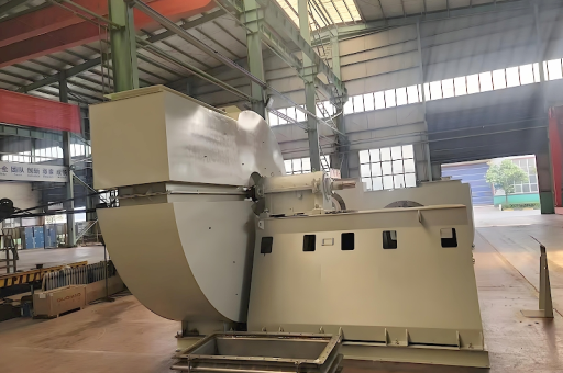
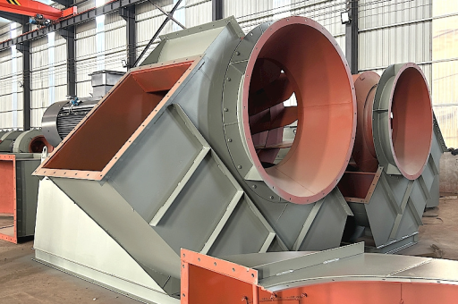
Housing and Volute
The fan housing is a spiral volute with a rectangular or circular inlet nozzle. The single inlet opening is positioned on the drive side. The housing is designed to withstand temperatures up to 200°C continuously, with optional refractory lining for gas temperatures up to 400°C.
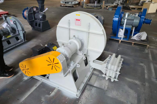
Coupling Assembly
The coupling can be a flexible elastomeric type (e.g., Lovejoy, Fenner) or a rigid steel gear coupling for high-torque applications. The coupling compensates for minor misalignment and reduces shock load transfer. In most modern installations, a spacer coupling is used to facilitate fan wheel removal without moving the motor.
Drive Motor
The motor is typically a squirrel-cage induction motor, IP55 or higher, equipped with Vibration Sensors (accelerometers) and bearing temperature probes (RTDs). Motor power ranges from 30 kW for small package boilers to over 1 MW for large utility boilers.
Working Principle
The induced draft fan generates a negative pressure (vacuum) at its inlet, typically –2 to –7 kPa (–8 to –28 in. w.g.) relative to atmosphere. This pressure gradient draws combustion gases through the boiler passes, superheater, economizer, air preheater, and particulate control devices. The gases exit the fan at a positive pressure of 0.5 to 1.5 kPa, sufficient to overcome stack draft losses.
Key Advantages Over Traditional Fan Configurations
| Feature | Single Inlet Coupling Driven ID Fan | Double Inlet ID Fan |
|---|---|---|
| Footprint | Compact, requires less floor area | Larger due to double-sided intake |
| Efficiency | 82–86% peak efficiency | 78–82% peak efficiency (due to uneven flow distribution) |
| Maintenance | Easier seal replacement, single shaft penetration | Two shaft seals, harder to access |
| Cost | Lower initial capital, fewer moving parts | Higher steel content, more mass balancing required |
| Vibration | Lower residual unbalance, simpler modal shape | Higher susceptibility to resonance from double mass distribution |
Engineers often choose the single inlet design when:
- Space is restricted (e.g., inside boiler house)
- Flue gas temperature is moderate (≤250°C)
- The system requires variable speed control via VFD (coupling-driven allows direct speed matching)
Critical Performance Metrics and Calculation Example
Key Metrics
- Volume Flow (Q): m³/s or ACFM (actual cubic feet per minute)
- Static Pressure Rise (Δp): Pa or in. w.g.
- Fan Power (P_fan): kW
- Fan Efficiency (η_fan): %
Sample Calculation
Given a small coal-fired boiler:
- Flue gas flow: 12 m³/s at 180°C
- System resistance: 3.2 kPa
- Gas density at 180°C: ~0.62 kg/m³
Fan static power:
[
P{static} = \frac{Q \times \Delta p}{\eta{fan}} = \frac{12 \times 3200}{0.84} = 45,714 \text{ W} \approx 45.7 \text{ kW}
]
At 0.85 power factor and motor efficiency 0.93, the required motor power would be:
[
P_{motor} = \frac{45.7}{0.93 \times 0.85} \approx 57.8 \text{ kW}
]
A 60 kW squirrel-cage motor with a gear coupling would be selected. The coupling size would be calculated based on torque:
[
T = \frac{P_{motor} \times 9550}{N} = \frac{60 \times 9550}{1480} \approx 387 \text{ Nm}
]
A flexible coupling with 1.2–1.5× service factor is recommended.
Installation Best Practices and Common Pitfalls
Foundations and Isolation
- Place the fan on concrete inertia base with vibration isolation pads (natural frequency < 10 Hz).
- Ensure baseplate level within 0.1 mm/m.
Ductwork Alignment
- Use expansion joints between duct and fan inlet to prevent thermal expansion stress.
- The single inlet side must have at least 2× duct diameter straight run upstream of the inlet to avoid flow swirl.
Coupling Alignment
- Perform laser alignment to within 0.05mm parallel and angular offset. Misalignment is the #1 cause of premature bearing failure in coupling-driven fans.
Common Pitfall: Oversized Motor
Many engineers specify a motor 20–30% larger than needed “just in case.” In reality, coupling-driven fans operating below 60% load exhibit poor efficiency (below 60% fan efficiency). Always size for actual operating point, not just max theoretical.
Maintenance, Vibration Analysis, and Troubleshooting
Recommended Maintenance Schedule
- Weekly: Check coupling alignment visible indicators, listen for unusual noise
- Monthly: Measure vibration velocity (mm/s RMS) at bearing housings (alarm: >7.1 mm/s, shutdown: >11.2 mm/s per ISO 10816-3)
- Quarterly: Inspect blades for erosion, check coupling wear (replace elastomeric elements every 2 years)
- Annually: Dynamic balancing of impeller, replace bearings, check shaft runout
Troubleshooting Common Issues
| Symptom | Likely Cause | Solution |
|---|---|---|
| High vibration at 1× RPM | Unbalance or misalignment | Rebalance impeller or realign coupling |
| High vibration at 2× RPM | Angular misalignment | Re-laser align, replace worn coupling spider |
| Overheating of drive-end bearing | Grease overfill or misalignment | Purge old grease, realign shaft |
| Motor current higher than design | Damper closed too far / blade fouling | Inspect blades, clean, re-open system dampers |
| Excessive noise from inlet | Flow separation or inlet swirl | Install straightener vanes in inlet duct |
Vibration Protection
Modern coupling-driven fans include Dual Accelerometers (ICP type) wired into the Bently Nevada or similar system. For critical boilers, a trend of increasing vibration (0.5 mm/s per month) indicates progressing imbalance, possibly due to blade erosion.
Frequently Asked Questions (FAQ)
Q1: Why choose a coupling-driven fan over a belt-driven fan for induced draft service?
A: Coupling-driven fans offer higher mechanical efficiency (no belt slip), quieter operation at high RPM (>1000 RPM), and less frequent maintenance (belt replacement is eliminated). However, coupling-driven designs require precise alignment and are less tolerant of overloads.
Q2: Can a single inlet fan be operated with a VFD (variable frequency drive)?
A: Yes. In fact, a VFD is recommended for variable load conditions. However, avoid running the fan below 30% rated speed, as inadequate cooling from the self-cooling impeller can overheat the motor. A separate forced cooling fan may be needed.
Q3: What is the typical service life of a single inlet coupling driven induced draft boiler fan?
A: With proper maintenance, the mechanical life exceeds 20 years. Critical components such as bearings (10–15 years) and impeller blades (5–8 years, depending on erosion) require periodic replacement.
Q4: How do single inlet and double inlet fans compare for temperature limits?
A: Single inlet fans can handle up to 250°C continuous (standard carbon steel housing) and up to 400°C with stainless steel or refractory lining. Double inlet fans have slightly higher maximum temperature capability (450°C) due to more effective shaft cooling from dual airflow paths.
Q5: What is the difference between induced draft and forced draft in the context of boiler fans?
A: Induced draft (ID) fans pull flue gases from the boiler, creating negative furnace pressure. Forced draft (FD) fans push ambient air into the burner. Single inlet coupling driven ID fans are exclusively used on the exhaust side, whereas FD fans are typically double inlet.
Conclusion: Future Trends and Industry Relevance
The Single Inlet Coupling Driven Induced Draft Boiler Fan remains the preferred choice for mid-scale industrial boilers and retrofitted plants due to its compactness, higher efficiency, and simpler maintenance. With increasing pressure to comply with emissions regulations (e.g., EPA Mercury and Air Toxics Standards, EU Industrial Emissions Directive), demand for reliable, high-performance ID fans continues to grow.
Modern trends include:
- Adoption of corrosion-resistant coatings (e.g., zirconia, ceramic spray) on blades for biomass or waste-to-energy boilers.
- Integration of smart sensors directly into the fan coupling spider (measuring torque and temperature).
- Use of carbon-fiber reinforced impellers to reduce weight and bearing loads.
For specific application selection, always consult the fan manufacturer’s software (e.g., Howden Fancom, fan selection guide). The single inlet coupling driven ID fan is a proven, reliable workhorse that, when correctly selected and installed, delivers decades of uninterrupted service.