This article's table of contents introduction:

- Table of Contents
- Introduction: Why FGD Systems Depend on Induced Draft Fans
- What Is an Induced Draft Single Inlet Centrifugal Fan?
- Key Design Features for Flue Gas Desulfurization Applications
- Performance Parameters: Flow, Pressure, and Efficiency
- Material Selection for Corrosion and Erosion Resistance
- Installation and Maintenance Best Practices
- Frequently Asked Questions (FAQ)
- Conclusion: Optimizing FGD Fan Performance for Long-Term Reliability
*
The Critical Role of Induced Draft Single Inlet Centrifugal Fans in Flue Gas Desulfurization Systems: Design, Performance, and Operational Best Practices*
Table of Contents
- Introduction: Why FGD Systems Depend on Induced Draft Fans
- What Is an Induced Draft Single Inlet Centrifugal Fan?
- Key Design Features for Flue Gas Desulfurization Applications
- Performance Parameters: Flow, Pressure, and Efficiency
- Material Selection for Corrosion and Erosion Resistance
- Installation and Maintenance Best Practices
- Frequently Asked Questions (FAQ)
- Conclusion: Optimizing FGD Fan Performance for Long-Term Reliability
Introduction: Why FGD Systems Depend on Induced Draft Fans
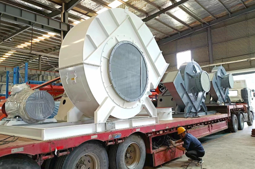
In modern coal-fired power plants and industrial boilers, Flue Gas Desulfurization (FGD) is a mandatory process to remove sulfur dioxide (SO₂) before exhaust gases are released into the atmosphere. At the heart of this system lies the Induced Draft Single Inlet Centrifugal Fan (ID-SI centrifugal fan). Without this fan, the entire FGD scrubbing process would fail to maintain negative pressure, resulting in poor gas-liquid contact, reduced SO₂ removal efficiency, and potential damage to downstream equipment.
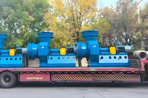
Unlike forced draft fans that push air into a system, induced draft fans pull flue gas through the FGD absorber tower, scrubber, and mist eliminator. The single inlet centrifugal design is particularly favored because it handles large volumes of corrosive, abrasive, and moisture-laden gas with minimal leakage and high static pressure capability. For operators seeking reliable desulfurization, choosing the correct ID fan is not optional—it is a regulatory and operational necessity.
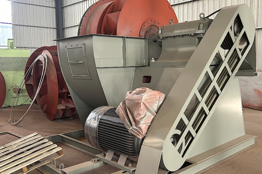
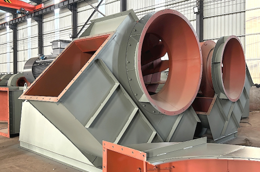
What Is an Induced Draft Single Inlet Centrifugal Fan?
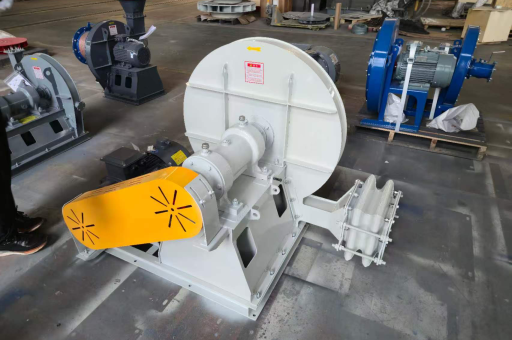
An Induced Draft Single Inlet Centrifugal Fan is a mechanical device that uses a rotating impeller to accelerate flue gas radially outward, converting kinetic energy into static pressure. In the FGD context, "induced draft" means the fan is located after the scrubbing equipment, pulling gas through the system rather than pushing it.
The "single inlet" designation indicates that gas enters the impeller from only one side (axial direction), which simplifies ductwork and reduces footprint compared to double-inlet designs. This configuration is ideal for FGD systems where space is constrained and gas flow is moderate to high (typically 100,000 to 600,000 m³/h). The fan's impeller, housing, and inlet cone are engineered to withstand the harsh chemical environment of wet FGD processes, including sulfuric acid mist, chloride ions, and high humidity.
Key components include:
- Backward-curved or airfoil blades for high efficiency
- Wear-resistant liners or coatings on the casing
- Shaft seals to prevent gas leakage into the atmosphere
- Vibration monitoring ports for predictive maintenance
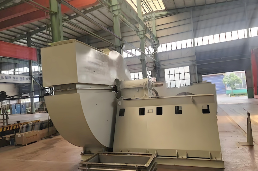
Key Design Features for Flue Gas Desulfurization Applications
When selecting or designing an ID centrifugal fan for FGD, three critical factors dominate the engineering approach:
1 Corrosion Protection
The flue gas after desulfurization is saturated with water vapor and contains residual SO₂, SO₃, and chlorides. These form sulfuric and hydrochloric acids when condensed. Therefore, the fan housing is typically constructed from duplex stainless steel (e.g., 2205) or fiber-reinforced plastic (FRP) . For extremely aggressive environments, rubber lining or high-temperature epoxy coatings are applied to the impeller and scroll.
2 Erosion Management
Fly ash particles and gypsum carryover from the slurry can erode fan blades at velocities exceeding 30 m/s. To combat this, leading blade edges are often hard-faced with tungsten carbide, and the inlet cone is designed with a replaceable wear ring. The fan's operating speed is kept below 900 rpm to minimize particle impact energy.
3 Temperature and Dew Point Control
FGD outlet gas temperatures typically range from 45°C to 70°C. If the gas temperature drops below the acid dew point (around 50°C–60°C for sulfuric acid), rapid corrosion occurs. Modern ID fans include temperature sensors and steam tracing coils on the casing to maintain the wall temperature above the dew point. Additionally, a fixed or variable inlet guide vane (IGV) is often installed to regulate flow without causing condensation.
Performance Parameters: Flow, Pressure, and Efficiency
For a typical 300 MW coal-fired unit, the induced draft fan must handle approximately 5 million m³/h of flue gas at a static pressure rise of 5–5 kPa. The single inlet centrifugal fan delivers this by operating at a specific speed (Ns) of 40–70, which balances high pressure and moderate flow.
Efficiency considerations:
- Aerodynamic efficiency of well-designed backward-curved blades exceeds 85%.
- Variable frequency drives (VFDs) can reduce power consumption by 20–30% at partial loads.
- Inlet duct geometry must be straight for at least three duct diameters upstream to avoid flow distortion and efficiency loss.
Example performance curve (normalized):
| Flow (m³/h) | Static Pressure (kPa) | Shaft Power (kW) | Efficiency (%) |
|-------------|-----------------------|------------------|----------------|
| 400,000 | 5.0 | 680 | 86 |
| 600,000 | 4.2 | 780 | 88 |
| 800,000 | 3.0 | 780 | 84 |
Material Selection for Corrosion and Erosion Resistance
The table below summarizes the typical materials used in ID single inlet fans for wet FGD service:
| Component | Material | Reason |
|---|---|---|
| Impeller | Duplex SS 2205 or SS 316L | High pitting resistance equivalent (PRE>35) |
| Casing | Carbon steel + 4mm rubber lining | Low cost + high corrosion resistance |
| Shaft | SS 410 or 17-4 PH | High strength, good corrosion fatigue life |
| Inlet cone | Hastelloy C-276 or ceramic-lined | Maximum resistance to acid wash attack |
| Bearings | Split roller + labyrinth seal | Easy replacement, no oil contamination risk |
Operators should specify NACE MR0175 compliance if sour gas (H₂S) is present. For offshore or high-moisture environments, consider upgrading the motor enclosure to IP56 and the fan housing to fully welded stainless steel.
Installation and Maintenance Best Practices
Pre-Installation Checklist
- Confirm fan inlet duct has a minimum straight run of 3× duct diameter.
- Install a drain pot at the lowest point of the fan casing to remove condensate.
- Ensure the isolation damper is placed between the FGD tower and fan inlet.
- Verify that the motor VFD cable is shielded to avoid electromagnetic interference.
Maintenance Schedule
- Weekly: Inspect drain lines for blockages; log vibration readings (bearing housing).
- Monthly: Measure casing temperature; check for acid pitting on external seams.
- Quarterly: Laser-align shaft and motor; replace bearing grease if contaminated.
- Annually: Perform borescope inspection of impeller blades; test anti-erosion coating thickness.
Common failure modes and preventions:
- Blade fatigue: Caused by resonance from variable speed operation. Mitigate by conducting a modal analysis during commissioning.
- Shaft seal leakage: Upgrade from carbon rings to double mechanical seals with pressurized water flush.
- Bearing seizure: Often due to water ingress. Install bearing isolators and check shaft grounding brushes.
Frequently Asked Questions (FAQ)
Q1: Why is a single inlet design preferred over double inlet for FGD?
A: The single inlet offers a more compact footprint, reduced risk of uneven flow distribution, and easier maintenance access. Double-inlet fans are typically used only when flow exceeds 800,000 m³/h.
Q2: Can I use a standard industrial fan for FGD service?
A: No. Standard fans lack the necessary corrosion-resistant coatings, blade geometry for wet gas, and seals for acidic environments. Using an off-the-shelf fan will lead to rapid failure within 3–6 months.
Q3: How often should the fan impeller be replaced?
A: With proper material selection (e.g., duplex stainless steel) and inlet guide vane control, an impeller can last 5–8 years. Heavily eroded environments with high fly ash content may require replacement at 3–4 years.
Q4: What is the energy saving potential with variable speed drives?
A: VFDs can reduce fan power consumption by 20–40% compared to inlet damper control, especially when the FGD unit operates at 60–80% load for extended periods. Payback period is typically 12–18 months.
Q5: How does the fan interact with the wind turbine in a hybrid renewable plant?
A: In a combined cycle or hybrid plant, the induced draft fan (powered by grid or backup steam) must maintain stable negative pressure even when wind turbine output fluctuates. Automatic load shedding controls ensure the fan does not stall during sudden power dips.
Conclusion: Optimizing FGD Fan Performance for Long-Term Reliability
The Induced Draft Single Inlet Centrifugal Fan for Flue Gas Desulfurization is a specialized, high-stakes component. Its failure can force a power plant to shut down or bypass environmental controls, leading to fines and reputational damage. By selecting fan materials based on actual flue gas chemistry, installing proper inlet guide vanes and VFDs, and adhering to a rigorous maintenance schedule, operators can achieve 25+ years of service life with minimal unscheduled downtime.
For new installations, always consult with fan manufacturers who provide aerodynamic performance guarantees under wet conditions and offer on-site commissioning support. Remember that the fan's reliability is directly tied to the quality of upstream mist elimination and drain management. When these subsystems are properly integrated, the ID fan becomes the quiet workhorse of your FGD system—operating efficiently, safely, and in full compliance with environmental regulations.
For additional technical specifications or to request a fan selection worksheet, search for reputable engineering resources in the power generation and wind turbine auxiliary equipment sector.