This article's table of contents introduction:

- Primary Function & Purpose
- Key Technical Characteristics & Design
- Harsh Operating Environment (Main Challenges)
- Common Failure Modes & Root Causes
- Operational & Maintenance Best Practices
- Key Performance Indicators (KPIs)
- Summary Table
This is a critical piece of equipment in the metallurgical industry, specifically within the iron and steelmaking process (sintering). The main exhaust fan (often called the Sintering Main Fan or Induced Draft Fan) is the "heart" of the sintering machine's gas system.
Here is a comprehensive technical breakdown of its role, purpose, design challenges, and operational issues.
Primary Function & Purpose
The main exhaust fan's sole purpose is to draw air (and combustion gases) down through the sinter bed on the moving pallets.
- Maintains Process Vacuum: It creates a strong negative pressure (typically 10-20 kPa or 1.5-3 psi) in the wind boxes beneath the sinter strand. This vacuum pulls air from the top of the bed down through the iron ore mix.
- Drives Combustion: This induced airflow provides the oxygen needed for the combustion of coke breeze (the solid fuel mixed into the ore) and the carbon in the sinter mix.
- Controls Process Speed: The fan speed (via a variable speed drive or hydraulic coupling) directly controls the "vertical combustion speed." This determines the production rate and sinter quality.
- Handles Waste Gas: It transports the hot, dust-laden, and corrosive off-gas from the wind boxes to the gas cleaning system (electrostatic precipitators or baghouses).
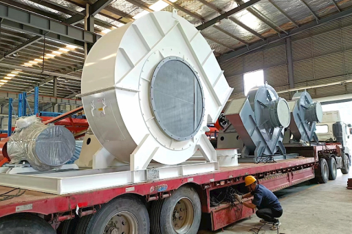
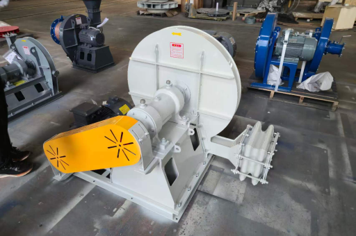
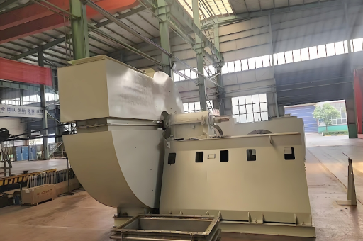
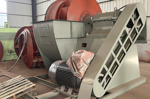
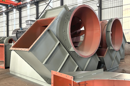
Key Technical Characteristics & Design
This is a physically massive and robust fan.
- Type: Centrifugal Fan (Radial or Backward-Curved Blades) . Forward-curved blades are almost never used due to dust, wear, and pressure requirements.
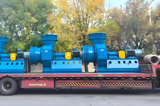
- Configuration:
- Single Suction or Double Suction: Large sinter plants will use a double suction fan to handle the enormous gas volumes (e.g., 10,000 to 25,000 m³/min or more).
- Single-Stage: For pressures up to ~15-20 kPa. Higher pressure may require a two-stage fan.
- Drive System: Very high power (e.g., 3,000 - 12,000 kW).
- Electric Motor: The primary driver.
- Variable Speed Control: Imperative.
- Hydraulic Coupling (Scoop Tube): Traditional, robust, but less efficient.
- Large VFD (Variable Frequency Drive): Modern, high efficiency (saves significant energy), better process control, but high initial cost.
- Rotor: Large diameter (3-5 meters), heavy, made of high-strength steel. The blades are often wear-lined (e.g., with ceramic tiles or hardfacing weld overlay) to resist erosion.
- Bearings: Typically sleeve bearings (journal bearings) with forced oil lubrication for reliability and long life under heavy loads.
Harsh Operating Environment (Main Challenges)
The main fan operates in one of the harshest environments in metallurgy. This leads to the primary operational problems.
- Severe Erosion (Wear): The off-gas contains fine, abrasive iron ore dust, coke fines, and limestone particles. Even with efficient precipitators, residual dust causes rapid wear of the fan blades, especially at the leading edges, blade root, and the inlet cone (shroud).
- Dust Deposition (Imbalance): Sticky, moist, or partially sticky dust (from condensation of water vapor and alkali chlorides) deposits unevenly on the fan blades. This causes:
- Mass Imbalance: Leading to severe vibration, bearing damage, and structural fatigue.
- Reduced Flow/Performance: The deposits change the blade profile, reducing fan efficiency.
- Corrosion: The off-gas contains SO₂, SO₃, HCl, HF, and water vapor. When the gas temperature drops below the acid dew point (typically 130-160°C for sulfuric acid), highly corrosive sulfuric acid condenses on the fan blades and housing. This, combined with erosion, leads to a phenomenon called erosion-corrosion.
- High Temperature: Normal operating temperature is 100-200°C, but can spike higher during upsets. The fan must be designed for this thermal stress.
- Large Vibration: Due to imbalance, wear, and misalignment. Vibration monitoring is mandatory.
Common Failure Modes & Root Causes
-
Vibration (Unplanned Shutdowns):
- Cause: Uneven dust buildup on the rotor (most common), bearing failure, blade cracking, or loose foundation bolts.
- Result: Immediately dangerous. Can lead to catastrophic blade failure (rotor tear-off) or bearing seizure.
-
Blade Erosion & Thinning:
- Cause: Abrasive wear from dust particles hitting the blades at high velocity.
- Result: Loss of fan performance (reduced flow and pressure), increased vibration, eventual blade crack and failure. This is the primary driver for maintenance cycles.
-
Shaft Fatigue Fracture:
- Cause: Continuous high-cycle bending stress from imbalance, misalignment, and thermal stress, leading to fatigue crack initiation and propagation.
-
Bearing Failure:
- Cause: Contamination of lubricating oil (with dust or water), loss of cooling, poor lubrication, excessive vibration transmitting through the shaft.
-
Housing Corrosion/Erosion:
- Cause: Direct impingement of dust and acid attack. Thin spots can lead to perforation, reducing efficiency and creating a safety hazard.
Operational & Maintenance Best Practices
To maximize reliability and service life, the following are critical:
- Strict Gas Temperature Control: The key is to operate the fan above the acid dew point, usually >150°C. Cold start-ups or low-load operation are especially dangerous. A pre-heating system (e.g., burning gas in the wind boxes) is often used to warm the fan before the main sinter process starts.
- Effective Pre-Dedusting: The Electrostatic Precipitator (ESP) or high-efficiency bag filter must be working perfectly. A significant dust carry-over reduction directly extends fan life. Uneven dust removal from ESP fields is a major cause of fan imbalance.
- Proactive Balancing:
- On-Line Balancing: Hydro-jet cleaning (water lances) to remove dust deposits from the rotor while running.
- Off-Line Balancing: Scheduled shut-down for manual cleaning and precision dynamic balancing on a dedicated balancing machine.
- Condition Monitoring:
- Vibration Analysis: Continuous monitoring (e.g., on bearings and housing) with alarms (velocity and acceleration). Trend analysis for imbalance and bearing wear.
- Thermography: Infrared cameras to detect hot spots on bearings, casings, and electrical connections.
- Oil Analysis: Regular sampling and analysis for wear metals (Fe, Cu, Pb) and contamination.
- Wear Protection:
- Surface Hardening: Application of hardfacing (e.g., Stellite, tungsten carbide) on the leading edges and wear zones of the blades.
- Ceramic Lining: Tiles or epoxy-based ceramic coatings on the fan housing, volute tongue, and inlet cone.
- Robust Lubrication System: Forced oil circulation with coolers, filtration, and oil mist or splash lubrication for bearings.
Key Performance Indicators (KPIs)
- Vibration Level: (e.g., less than 4.5 mm/s RMS for new, increased alarm at 7.1 mm/s).
- Bearings Temperature: (Alarm at 80-85°C, Trip at 95-100°C).
- Current/Amp Load: (Monitors fan loading and blade condition/flow).
- Gas Inlet Temperature: (Monitored for acid dew point risk).
- ESP Outlet Dust Concentration: (The single biggest influence on fan wear; e.g., target < 30 mg/Nm³).
Summary Table
| Feature | Description / Challenge |
|---|---|
| Type | Centrifugal, Backward-Curved, Double Suction |
| Environment | Hot (100-200°C), Corrosive (SOx/HCl), Abrasive (dust) |
| Main Failure | Vibration due to dust imbalance; Blade wear |
| Most Critical Issue | Operating temperature below the acid dew point |
| Key Maintenance | On-line balancing/proactive cleaning; Vibration analysis; Hardfacing/ceramic lining |
| Drive | Large Motor (5-12 MW) + VFD / Hydraulic Coupling |
| Industry Term | Sintering Main Fan, ID Fan, or Waste Gas Fan |
This fan is a vital, high-maintenance, and expensive asset. Its failure directly stops the sinter plant, which in turn significantly impacts blast furnace production. Therefore, a meticulous, condition-based maintenance strategy is essential.