This article's table of contents introduction:

- Core Application: Flue Gas Recirculation (FGR)
- Typical System Parameters & Design Points
- Fan Type & Construction (Recommended)
- Drive & Motor Requirements (110 kW)
- Critical Considerations for a 110kW FGR Fan
- Typical Procurement Specification Outline
- Summary for a 110 kW FGR Fan:
This appears to be a request for technical specifications, selection criteria, or operational details regarding a 110 kW Flue Gas Recirculation (FGR) Fan.
Note: I am generating a detailed, generalized technical sheet based on standard industrial practices for this type of application. If you have a specific OEM (e.g., Howden, TLT, Greenheck) or a specific fuel type (coal, gas, biomass), please provide that for a more accurate response.
Core Application: Flue Gas Recirculation (FGR)
This fan is a critical component of an FGR system used primarily in:
- NOx Reduction: Recirculating a portion of the exhaust gas back into the combustion zone lowers the flame temperature, reducing thermal NOx formation.
- Steam Temperature Control: In boilers, FGR can help regulate reheat steam temperatures without burner tilts or attemperation sprays.
- Draft Control: Assisting in maintaining the proper negative pressure in the furnace or boiler.
Typical System Parameters & Design Points
For a 110 kW (approx. 150 HP) motor, the fan is likely a medium-to-large industrial fan. Here are common design assumptions:
| Parameter | Typical Value | Notes |
|---|---|---|
| Power | 110 kW (150 HP) | Motor shaft power, typically includes a 1.15 Service Factor (SF). |
| Flow Rate | 15,000 – 30,000 CFM (25,000 – 50,000 m³/h) | Highly dependant on system resistance. |
| Static Pressure | 10 – 30 inWG (2.5 – 7.5 kPa) | Moderate pressure; FGR is usually a low-to-medium pressure circuit. |
| Gas Temperature | 150°C – 400°C (300°F – 750°F) | Critical Parameter. Fan must be rated for the peak flue gas temperature, including upset conditions. |
| Gas Density | 5 – 0.9 kg/m³ | Hot, low-density gas requires more power for the same volumetric flow (fan laws). |
| Material Type | 316L Stainless Steel or Alloy 625 | Required for corrosion resistance from acidic condensate (Sulfuric, Nitric). Carbon steel fails quickly. |
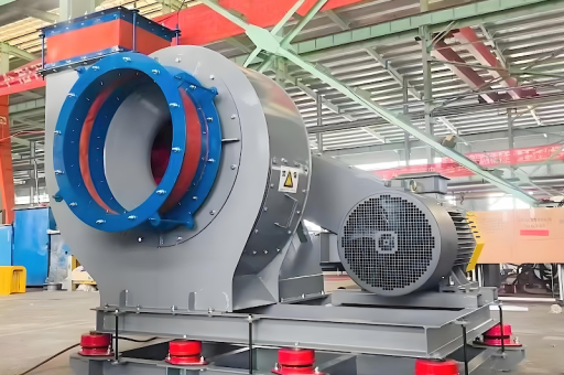
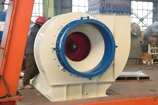
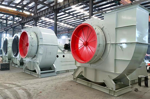
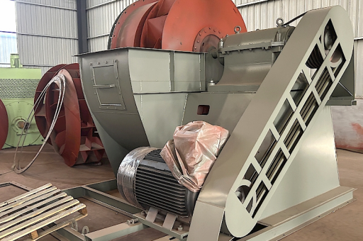
Fan Type & Construction (Recommended)
Fan Type: Centrifugal
- Wheel Design: Radial Blade (for dirty gas) or Backward Inclined (AF) for higher efficiency.
- Housing: Spiral scroll with a drain connection (for condensate).
- Shaft Seal: Labyrinth or carbon ring seal to prevent flue gas leakage into the bearing housing or environment.
Material of Construction (Must specify for 110 kW unit):
- Impeller & Shroud: SS316L (minimum). For high sulfur fuel, Hastelloy C-276 or Duplex 2205 is recommended.
- Shaft: EN8 (mild steel) with a stainless steel sleeve under the seal area, or full SS316.
- Casing: SS316L (lower temp) or clad carbon steel (higher temp/cost).
- Insulation & Lagging: Required if gas temp > 60°C (140°F) to protect personnel and prevent condensation.
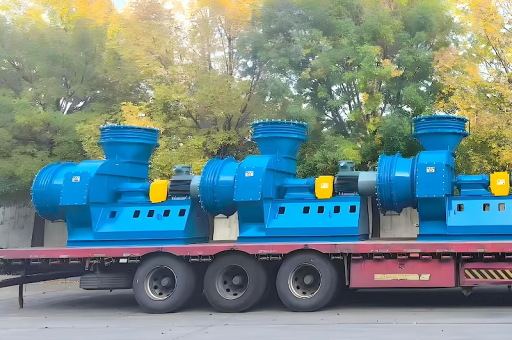
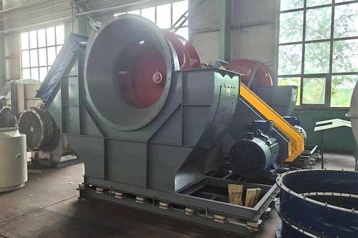
Drive & Motor Requirements (110 kW)
- Motor Type: TEFC (Totally Enclosed Fan Cooled) or TENV.
- Voltage: 400V / 690V / 3.3kV / 6.6kV (Depending on motor size and plant grid).
- Speed Control: VFD (Variable Frequency Drive) is mandatory.
- Why? FGR flow must be precisely controlled to meet NOx emissions across boiler loads.
- Bearing Type: Split roller bearings (SNL or SAF type) with external grease blocks or circulating oil lubrication (for high temp).
- Coupling: Flexible diaphragm coupling (avoids thermal stress transmission from the fan shaft to the motor).
Critical Considerations for a 110kW FGR Fan
- Acidic Condensation (The "Killer"): This is the #1 failure mode.
- Problem: Flue gas contains SO₂ and NOx. When the fan casing or wheel is below the acid dew point (~120°C for sulfur, lower for acid), it forms corrosive acid.
- Solution: Continuous casing heating (steam or electric tracing) OR strict pre-heating before introducing gas. The fan must never idle with cool gas inside.
- Thermal Expansion:
- A 110kW fan moving 300°C gas will expand significantly.
- Required: Flexible expansion joints at the fan inlet/outlet.
- Inboard Bearing: Must float axially; the outboard bearing is fixed.
- Vibration Monitoring:
- Mandatory: Accelerometers on both bearing housings (H and V). Alarm at ~4.5 mm/s RMS, Trip at ~7.5 mm/s RMS. Imbalance from erosion/corrosion is the most common failure.
- Dampers:
- Inlet Box Damper: Variable inlet vanes (IVs) for energy-efficient control (used alongside VFD for backup or turndown).
- Outlet Damper: Guillotine or louver-type for isolation during maintenance (must be motorized).
Typical Procurement Specification Outline
If you are writing a specification for this fan, include these clauses:
- Performance: Certified test according to AMCA 210 or ISO 5801.
- Wheel Over-speed: Tested to 110% of max continuous speed.
- Stress Analysis: Finite Element Analysis (FEA) for the wheel at max speed and temp.
- NPSH? (not usually an issue for gas, but ensure no cavitation if operating near saturated steam conditions in the gas).
- Welding: ASME Section IX or EN ISO 15614. Full welding procedure qualification.
- Accessories: Drain valve (NPT 2" min), lifting lugs, inspection door, vibration studs.
Summary for a 110 kW FGR Fan:
You are dealing with a severe-duty, high-temperature centrifugal fan. The single biggest cost driver and failure point is material selection for corrosion resistance. A 110kW fan in 316L SS will cost roughly 2.5x that of a carbon steel fan of the same size. Do not use carbon steel for FGR.
Do you need a specific calculation (e.g., "Will this fan work at 180°C with a pressure drop of 15 inWG?") or a specific drawing standard?