This article's table of contents introduction:

- The Role of the Fan in a Rotary Kiln System
- The Energy Efficiency Paradox: High Temperature vs. High Flow
- Critical Strategies for Improving Energy Efficiency
- Major Challenges & Potential Failures
- Summary of Key Metrics & Targets
- Conclusion
This is a highly specific and technical topic at the intersection of thermal process engineering, fluid dynamics, and materials science.
Here is a detailed breakdown of the relationship between Energy Efficiency, Industrial Rotary Kilns, and High-Temperature Centrifugal Fans, including the key challenges and solutions.
The Role of the Fan in a Rotary Kiln System
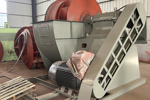
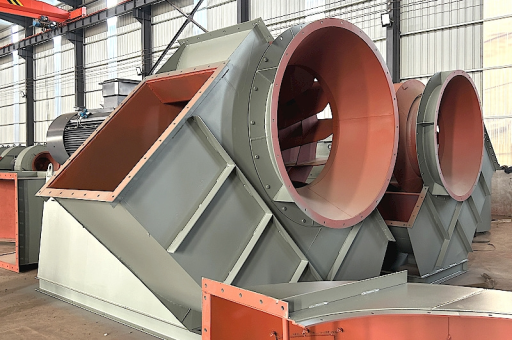
The high-temperature centrifugal fan is not just an accessory; it is the "lungs" of the kiln system. Its primary functions are:
- Combustion Air Supply: Forcing primary and secondary air into the burner for fuel combustion.
- Induced Draft (ID): Pulling hot combustion gases, flue gases, and process dust through the kiln, preheater (if applicable), and pollution control equipment (baghouse, ESP, scrubbers).
- Cooling: In the clinker cooler (cement) or product cooler, fans force ambient air through the hot product to recover heat and cool the product.
- Pneumatic Transport: Moving raw material feed or collected dust.
The Energy Efficiency Paradox: High Temperature vs. High Flow
The centrifugal fan is often the single largest electrical load in a rotary kiln system (after the kiln drive motor itself). The efficiency challenge is a battle against physics:
-
The Affinity Laws (Why small changes matter):
- Flow is proportional to speed (RPM).
- Pressure is proportional to the square of speed (RPM²).
- Power is proportional to the cube of speed (RPM³).
- Implication: A 10% reduction in fan speed reduces power consumption by over 30%. The primary goal is to run the fan as slow as possible while still maintaining proper draft and combustion.
-
High Temperature Density Effect:
- Hot air (e.g., 400°C / 750°F) is much less dense than cold air.
- The fan must move a mass flow of gas. To move the same mass of gas at higher temperature, the fan must move a larger volumetric flow rate. This requires significantly more power.
-
High Temperature Materials:
- Standard fans fail. Impellers must be made of stainless steel (e.g., 310S), Inconel, or Hastelloy to avoid creep and thermal fatigue.
- Shaft cooling (via a cooling wheel or water jacket) is required to prevent heat from traveling to the bearings and motor.
Critical Strategies for Improving Energy Efficiency
To maximize efficiency in this harsh environment, engineers focus on three areas: Motor/Drive, Fan Design, and System Control.
A. Motor & Drive Efficiency (The "Power Source")
- VFDs (Variable Frequency Drives) are MANDATORY. Dampers or guide vanes waste energy by creating artificial restriction. A VFD directly controls the motor speed, aligning power consumption precisely with demand.
- Savings: 20-40% compared to damper control, especially at partial loads.
- High-Efficiency Motors (IE4 / IE5): Use synchronous reluctance or premium efficiency induction motors. The payback is fast due to the high duty cycle (24/7 operation).
- Belt vs. Direct Drive: High-temperature fans often use direct drive to avoid belt slippage and heat-related belt wear. Modern direct couplings have near-zero losses.
B. Aerodynamic Design (The "Fan Shape")
- Backward-Curved Centrifugal Impellers: These are the standard for efficiency. They are less prone to dust buildup (a major issue in kilns) and have a non-overloading power characteristic.
- Airfoil Blades: For clean gas applications (e.g., after a baghouse), airfoil-bladed centrifugal fans are the gold standard, achieving >85% static efficiency.
- Volute Cut-Off Optimization: The gap between the impeller tip and the volute housing is critical. A poorly optimized cut-off creates turbulence and noise, wasting energy.
- Inlet Cone & Inlet Box: Smooth, aerodynamic inlet boxes (often with a turning vane) reduce entrance losses, which can be significant on large ID fans.
C. System Control & Process Integration (The "Brain")
- Draft Control Strategy:
- Use Oxygen (O₂) sensors in the kiln exhaust. The VFD modulates the ID fan speed to maintain a precise O₂ target (e.g., 2-3%). Too much excess air wastes fuel by heating useless nitrogen; too little causes incomplete combustion and ring formation in the kiln.
- Maintain a slight negative pressure at the kiln hood to prevent hot gas blowback.
- Cold Air Infiltration: Leaks in the kiln hood, seals, or preheater allow cold air to enter. This cold air must be heated by the process, wasting fuel, AND the fan must work harder to move this extra volume. Sealing is a simple, high-ROI efficiency measure.
- Heat Recovery Integration:
- Clinker Cooler Fan Control: Fans in the cooler preheat the combustion air (Secondary Air). Carefully controlling cooler fans to deliver the correct air temperature and pressure to the kiln burner reduces overall fuel consumption.
- Hot Gas Bypass: Some systems use the high-temperature fan to draw a slipstream of hot gas for drying raw materials in a separate mill, reducing the need for a dedicated heater.
Major Challenges & Potential Failures
High-temperature operation creates specific failure modes that directly impact efficiency:
- Impeller Creep & Fatigue: At sustained high temperatures ( > 500°C), steel loses its strength. The impeller can slowly deform ("creep") or suddenly crack due to thermal cycling (start/stop).
- Dust Build-Up (Unbalance): Cement, lime, or mineral dust sticks to the impeller blades. This causes severe vibration, forces the fan to run slower (reducing flow), and damages bearings. Efficiency plummets.
- Solution: Coatings (e.g., Teflon, ceramic) or air-swept inlets to prevent sticking.
- Shaft & Bearing Cooling: If the shaft cooling wheel fails, heat travels along the shaft to the bearings. Bearing failure leads to unplanned downtime. Water-cooled bearings (jackets) are common but consume water and create waste heat.
- Corrosion: Condensation of sulfuric acid (from sulfur in the fuel) on the impeller at certain temperature ranges (acid dew point) can rapidly eat away the metal.
Summary of Key Metrics & Targets
| Metric | Target / Best Practice | Efficiency Impact |
|---|---|---|
| Fan Static Efficiency | > 85% (for clean gas) | Direct electrical saving |
| VFD Utilization | 100% (mandatory) | 20-40% reduction vs. dampers |
| Excess O₂ (kiln exit) | 5% - 3.0% | Balances fuel use & draft work |
| Cold Air Leakage | < 5% of total flow | Reduces fan work & fuel use |
| Impeller Tip Speed | Optimized for application | Avoids oversizing & wasted power |
Conclusion
To achieve Energy Efficiency in an Industrial Rotary Kiln with a High Temperature Centrifugal Fan:
- Control the speed, not the flow (VFD is non-negotiable).
- Minimize the temperature rise (seal the kiln to prevent cold air infiltration).
- Choose the correct fan design (backward-curved, airfoil, high-strength alloy).
- Maintain balance (use coatings or air-swept inlets to prevent dust buildup).
The ROI on upgrading an existing kiln fan system to a modern, VFD-controlled, high-efficiency unit is typically 1-3 years, driven by savings in both electrical power and fuel consumption.