
This article's table of contents introduction:
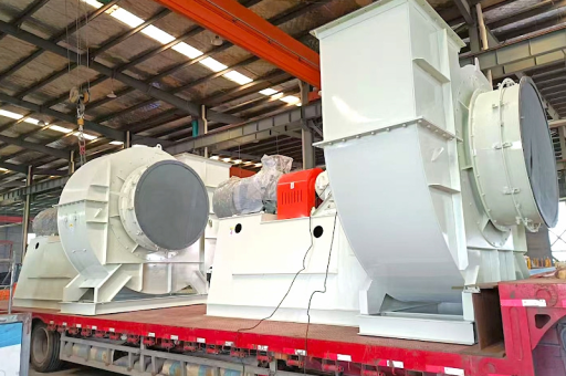
- What is an Induced Draft (ID) Fan?
- Key Characteristics of "Large Capacity" ID Fans
- Types of Large-Capacity ID Fans
- Why is it a Critical Component? (Operating Conditions)
- Control Strategy
- Common Problems and Maintenance Focus
- Key Specifications for a 660 MW Plant (Example)
- Summary
This is a detailed technical overview of Induced Draft (ID) Fans with Large Capacity, specifically for use in thermal power plants.
What is an Induced Draft (ID) Fan?
An Induced Draft (ID) Fan is a mechanical draught system located at the outlet of the flue gas system (after the electrostatic precipitator or bag filter). Its primary function is to pull (induce) the flue gases (combustion products) through the boiler, economizer, air preheater, and pollution control equipment, and finally discharge them into the chimney.
Key Difference from FD Fan: The Forced Draft (FD) Fan pushes air into the furnace. The ID Fan pulls the resulting hot gases out of the furnace. The ID Fan maintains a slightly negative pressure (draft) inside the furnace to prevent hot gases from escaping into the boiler house.
Key Characteristics of "Large Capacity" ID Fans
In modern thermal power plants (e.g., 500 MW, 660 MW, or 800 MW units), the ID Fans are massive pieces of rotating machinery.
- Size: Impeller diameters can range from 5 to 5 meters (11-16 feet) .
- Power Rating: Motor power is typically in the range of 3,000 kW to 7,000 kW (4,000 to 9,400 HP) .
- Flow Rate: Handles enormous volumes of flue gas, typically 500 to 1,200 m³/s (for a 500 MW unit).
- Pressure: Creates a pressure rise (differential) of approximately 400 to 800 mmWC (millimeters of water column) .
Types of Large-Capacity ID Fans
Two main designs are used for large thermal plants:
A. Axial Flow Fans (Most Common for Modern Large Units)
- Design: Air flows parallel to the fan axis. They feature a hub with multiple blades.
- Key Feature: Variable Pitch (VP) Blades. The angle of the blades can be adjusted hydraulically or pneumatically while the fan is running. This allows for precise control of the gas flow without using inefficient dampers.
- Advantages:
- Excellent efficiency over a wide operating range.
- Compact design relative to centrifugal fans for the same duty.
- Very good for regulating the furnace draft (fast response).
- Disadvantages:
- More complex and expensive.
- Higher maintenance requirements (hydraulic system for blade actuation).
- More sensitive to erosion from fly ash.
B. Centrifugal Fans (Used in Older or Smaller Units)
- Design: Air enters the center (eye) of the impeller and is flung outward by radial blades. The most common type for this duty is a Backward Curve / Backward Aerofoil (BC/BA) design or a Radial Tip (RT) design.
- Key Feature: Flow is controlled by inlet guide vanes (IGVs) or variable-speed drives (VFDs). Backward-curved blades are more efficient but prone to erosion. Radial-tip blades are more robust for high-particulate gases.
- Advantages:
- Very robust and can handle heavy, dusty flue gases.
- Simple construction.
- Lower initial cost.
- Disadvantages:
- Lower efficiency at part loads compared to axial VP fans.
- Larger and heavier for the same capacity.
Why is it a Critical Component? (Operating Conditions)
The ID Fan operates under the harshest conditions in the plant:
- Hot & Corrosive Gas: The gas temperature after the Air Preheater is typically 130-160°C (266-320°F) . The gas contains sulfur dioxide (SO₂) and water vapor, which can form sulfuric acid if the temperature drops below the acid dew point.
- Abrasive Fly Ash: Even after Electrostatic Precipitators (ESPs) or Bag Filters, a significant amount of fine, abrasive fly ash passes through the fan blades, causing severe erosion.
- Negative Pressure: The fan creates suction. If the fan fails or trips, the furnace pressure rises instantly, potentially causing a "furnace puff" (explosion) or pushing flames out of boiler openings.
Control Strategy
- Primary Control: The control of the ID fan is directly tied to furnace draft.
- Feedback: A furnace pressure transmitter sends a signal to the Distributed Control System (DCS).
- Action: The DCS changes the blade angle (for axial) or IGV position (for centrifugal) to maintain the setpoint (e.g., -2 to -5 mmWC).
- Coordination: The ID fan control must be tightly coordinated with the FD fan and the PA fans to maintain the air/fuel ratio and furnace pressure. A "master pressure controller" typically balances the ID and FD fans.
Common Problems and Maintenance Focus
| Problem | Cause | Mitigation |
|---|---|---|
| Blade Erosion | High-velocity fly ash particles hitting the blade leading edges. | - Use of hardfacing (Stellite/Chromium carbide) coatings on blades. - Regular thickness measurements via ultrasonic testing. - Rotating the rotor 180° (for axial) to distribute wear. |
| Imbalance & Vibration | Uneven ash buildup (fouling) on blades; erosion; bearing wear. | - Online water washing systems (to remove wet/damp ash). - Regular vibration monitoring (proximity probes). |
| Blade Jamming (Axial VP) | Binding in the blade actuation mechanism due to ash ingress or corrosion. | - Regular lubrication of the hub mechanism. - Clean hydraulic oil. |
| Shaft & Bearing Failure | High temperatures causing oil degradation; fatigue. | - High-grade bearing lubrication systems with coolers. - Continuous temperature monitoring. |
| Fan Stall / Surge | Operating too far from the design point (low flow against high pressure). | - Proper control logic to prevent operation in stall region. - Use of a recirculation duct if necessary. |
Key Specifications for a 660 MW Plant (Example)
- Type: 2 x 50% capacity (Two fans share the load; one can support the plant at lower load) or 1 x 100% (Less common, no redundancy).
- Model: Single-stage, double-inlet (for axial) or double-inlet double-width (DIDW) for centrifugal.
- Flow: ~800 m³/s.
- Pressure Rise: 600 mmWC.
- Motor: 4,500 kW, 6.6 kV, 990 RPM (for centrifugal) or 330 RPM with gearbox (for axial).
- Material: Corten or Weathering Steel (for corrosion resistance).
- Drive: Typically a constant-speed motor with hydraulic blade pitch control (axial) or a variable-frequency drive (VFD) for high-efficiency centrifugal designs.
Summary
The Induced Draft Fan is the exhaust of the thermal power plant. Without it, the boiler cannot operate. In large capacity plants, the variable-pitch axial fan has become the industry standard due to its high efficiency and responsivity, despite its complexity. The fan's reliability is heavily dependent on erosion management and vibration control due to the abrasive and corrosive nature of flue gases.





