
This article's table of contents introduction:
- The Core Problem: The Fan as an Ignition & Propagation Point
- The Solution: A Layered Protection Strategy
- Specific Recommendations for a "Single Inlet High Volume" Fan
- The Most Common & Effective Setup
- Critical Warning: Never Isolate the Fan!
- Final Step: Documentation & Analysis
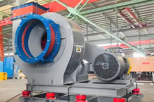
This is a critical topic in industrial safety. A Single Inlet High Volume Dust Collector Fan is typically a centrifugal fan (often a radial or backward-curved blade design) used to move large volumes of air through a baghouse or cartridge dust collection system.
When handling combustible dusts (metal, wood, carbon, food, etc.) or explosive gases, the fan itself can become both an ignition source and a point of explosion propagation.
Here is a comprehensive guide to explosion protection for this specific type of fan.
The Core Problem: The Fan as an Ignition & Propagation Point
- Ignition Sources: The fan is a mechanical device.
- Mechanical Sparks: Metal-to-metal contact (fan wheel rubbing on the housing) due to bearing failure, imbalance, or foreign objects.
- Static Electricity: Dust particles moving at high velocity generate static charge on the fan wheel and housing.
- Friction/Overheating: Blow-up (dust buildup on the impeller causing imbalance and friction) or bearing overheating.
- Explosion Propagation: A dust explosion that starts in the ductwork or the collector housing can travel back to the fan. The fan acts as a "flame path accelerator," making the explosion more violent.
The Solution: A Layered Protection Strategy
You cannot rely on a single safety device. You must use a layered strategy, typically governed by standards like NFPA 68 (Deflagration Venting), NFPA 69 (Explosion Prevention Systems), and ATEX (Europe).
Preventing the Explosion (NFPA 69)
This is the first line of defense.
- Spark Detection & Extinguishing: Install spark detectors in the ductwork before the fan. If a spark is detected, a water spray or suppression system activates to quench the spark before it reaches the fan or collector.
- Crucial: The system must have a very fast response time (milliseconds).
- Foreign Object Removal: A magnetic separator or screen (protected by a pressure switch) in the inlet duct to catch tramp metal that could cause sparks.
- Static Grounding & Bonding: The fan housing, ductwork, and every component must be electrically bonded and connected to a true earth ground. Use a conductive fan wheel (carbon steel or stainless) for metal dusts.
- Avoiding Friction: Use a well-maintained, non-sparking fan design:
- Material: For metal dusts, use a non-ferrous impeller (e.g., aluminum-bronze or stainless steel) in a steel housing. Note: NFPA 484 for combustible metals specifically requires this.
- Tolerances: The gap between the impeller and the inlet cone must be large enough to prevent rubbing under all operating conditions (including thermal expansion and bearing wear).
- Airflow Control: Use a Variable Frequency Drive (VFD) to control speed gently. Avoid running the fan in its "stall" region, which can cause severe vibration and rubbing.
Containing the Explosion
This is the secondary line of defense if prevention fails.
- Design for Pressure (Pmax): The fan housing must be designed to withstand the maximum explosion pressure without rupturing. This is very difficult and expensive for large, high-volume fans. It is often not the primary choice.
- Isolation Valves: Install explosion isolation valves (mechanical or chemical) in the ductwork both upstream and downstream of the fan. This prevents flame and pressure from traveling back to the work area or forward to the collector.
- Mechanical: Flap valves, flap gates, or pinch valves that close rapidly upon detecting a pressure wave.
- Chemical: A chemical suppressant (e.g., sodium bicarbonate) is injected by a fast-acting pressure detector to extinguish the flame and stop propagation.
Relief Venting (The Most Common & Practical Solution)
This is the standard approach for most dust collector fans. You let the explosion safely exit the housing.
- Ductwork/Fan Housing Venting:
- Location: The explosion vent must be installed directly on the fan housing or on the ductwork immediately adjacent to the fan inlet/outlet.
- Design (NFPA 68/EN 14491): The vent is a panel or door that opens at a low pressure (e.g., 0.5 psi / 3.5 kPa). It is held closed by a spring, magnetic latch, or chemical seal, not by bolts.
- Direction: The vent must discharge to a safe, unoccupied area (outside the building, away from equipment and personnel). A blast deflector or duct is often used to direct the flame and pressure safely.
- Rotor Design:
- Open vs. Closed Wheel: For dusts, an open radial blade wheel is preferred over a backward-curved airfoil wheel. Open wheels are much less likely to clog, reducing the risk of blow-up and the resulting sparks/overheating.
- Blow-Up Prevention: The fan must be sized correctly. The fan curve must ensure it operates well to the right of its peak pressure (the "surge" region). This prevents dust from building up on the blades.
Suppression (Active Protection)
If venting is impossible (e.g., the fan is indoors, and you can't duct the vent outside safely) or as a backup.
- Chemical Suppression System: Pressure detectors (Pmax sensors) mounted in the ductwork or fan housing trigger a high-s rate suppression agent (e.g., powder or water mist) to be injected into the fan housing, smothering the explosion before it can build to maximum pressure.
Specific Recommendations for a "Single Inlet High Volume" Fan
| Component | Explosion Protection Strategy | Key Standard/Notes |
|---|---|---|
| Impeller | Use a non-sparking material (aluminum-bronze, stainless) for metal dust. Maintain large clearance (gap). | NFPA 484, 664 |
| Inlet Duct | Spark detection & suppression. Isolation valve (mechanical or chemical). | NFPA 69 |
| Fan Housing | Deflagration vent sized per NFPA 68/EN 14491. Must discharge to a safe outdoor zone. | NFPA 68 |
| Outlet Duct | Isolation valve (to protect the downstream filter/collector). | NFPA 69 |
| Electrical | Motor & VFD must be rated for the correct Class/Division/Zone of the dust. | NEC / IEC |
| Bearing | Use continuous bearing temperature monitoring (RTD sensors) with an alarm/shutdown. | Best Practice |
| Static | Full bonding & grounding of all components. | NFPA 77 |
The Most Common & Effective Setup
- Inlet: Spark detector + Chemical Suppression (or Water Extinguishing) system on the duct before the fan.
- Fan: Deflagration vent panel on the fan housing, discharging to a safe outdoor area. Non-sparking impeller.
- Outlet: Mechanical isolation flap valve on the duct between the fan and the filter collector.
Critical Warning: Never Isolate the Fan!
Do not put an isolation valve or damper right at the fan inlet that can close automatically. If the fan is running and the valve closes, it will immediately create a vacuum, cause the fan to stall, generate severe vibration, and almost certainly cause a spark or impeller rupture. All isolation valves must be interlocked with the fan starter so they cannot close while the fan is running, or they must be designed to fail-open on power loss.
Final Step: Documentation & Analysis
You must perform a Dust Hazard Analysis (DHA) for the entire system per NFPA 652. This will formally determine:
- The Kst (explosion severity) of the dust.
- The Pmax of the dust.
- The required vent area for the fan housing.
- The required isolation distance between the fan and the collector.
Do not attempt to design these systems without the guidance of a qualified fire protection engineer specialized in combustible dust. The consequences of a mistake are catastrophic.





