
This article's table of contents introduction:
- The Core Components Defined
- How the System Works (The Physics)
- Why this System is Used (The Advantages)
- Potential Failure Points & Design Considerations
- Summary Diagram (Conceptual)
This is a description of a specific industrial or HVAC system component configuration. Let's break down what each part means and how the system functions as a whole. The core concept involves thermal protection for the equipment utilizing forced convection and conduction.
Here is the detailed explanation:
The Core Components Defined
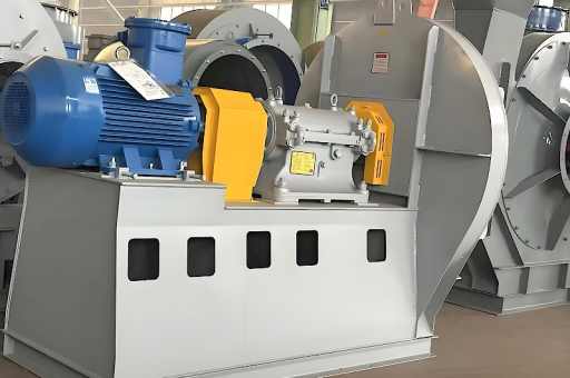
- AC Motor: The prime mover. An Alternating Current electric motor provides the rotational force (torque and speed) to drive the system.
- Coupling: A mechanical device (e.g., flexible jaw, grid, or tire coupling) that connects the motor's shaft to the fan's shaft. It transmits power while compensating for minor misalignments.
- High Pressure Centrifugal Fan: The workhorse. This is a fan designed to generate significant static pressure (often measured in inches of water gauge or kPa), used to move air against resistance (ductwork, filters, material handling). The impeller spins inside a housing.
- Oven Wall: This is the structural boundary of the oven. The fan is mounted on or near this wall. The wall itself is a heat source due to conduction from the hot oven interior.
- Cooling: The mechanism by which heat is removed from the "Oven Wall," specifically the area surrounding the fan and motor mounting.
How the System Works (The Physics)
The critical engineering challenge here is thermal management. An oven fan is exposed to high temperatures from the process heat. If that heat conducts through the oven wall and travels up the fan shaft to the bearings, or radiates to the motor, the equipment will fail.
The Cooling Mechanism (Forced Convection via the Fan):
The cooling is achieved not by a separate water or refrigerant system, but by the aerodynamics of the fan itself.
- High-Pressure Airflow: The centrifugal fan draws in air (often cooler ambient air) from the oven's exterior.
- Air Sweeps the Wall: This intake air is forced to flow across the face of the oven wall and the base of the fan housing before entering the fan inlet.
- Heat Extraction: As this cooler air moves across the hot metal of the oven wall and the fan's mounting plate, it absorbs heat via forced convection. The high velocity of the air (driven by the fan's high-pressure capacity) significantly increases the heat transfer coefficient, making cooling very efficient.
- Air Gap: In some designs, a specific gap or plenum is created between the oven wall and the fan/motor mounting structure. The fan's suction pulls cooling air through this gap, creating a "cold air barrier" that prevents the hot wall from directly heating the fan bearings and motor.
Why this System is Used (The Advantages)
This design is common in high-temperature ovens, dryers, kilns, and industrial furnaces.
- Protects the Motor: The motor is designed to operate in a specific ambient temperature (e.g., 40°C / 104°F). Without cooling, the radiated and conducted heat from the oven would quickly exceed its rating, causing it to overheat, trip thermal overloads, or burn out the windings.
- Extends Bearing Life: The fan shaft bearings are the most temperature-sensitive part. Heat degrades grease and causes thermal expansion, leading to seizing. The cooling airflow keeps the bearing housing at a safe operating temperature.
- Prevents Heat Conduction: The coupling and the air gap help break the direct thermal path. The coupling itself is a poor conductor of heat (compared to a solid steel shaft).
- Simple and Reliable: No need for external water lines, compressed air, or expensive heat exchangers. The cooling is inherent to the system's operation.
Potential Failure Points & Design Considerations
To ensure this system works, engineers must consider:
- Ambient Air Temperature: If the air being drawn in for cooling is already hot (e.g., the room is 100°F), the cooling capacity is severely reduced.
- Flow Path Blockage: If the cooling air intake grilles or gaps are blocked by dust, insulation, or debris, the fan will have no cooling air, leading to rapid bearing failure.
- Heat Soak on Shutdown: The biggest danger is when the fan stops. The oven is still hot, and without the cooling airflow, heat soaks into the stationary shaft and destroys the quill or bearings. A system often runs a "post-purge" cycle.
- Coupling Type: A flexible coupling made of a material with low thermal conductivity (like a polymer or urethane spider) is superior to a metal grid coupling for preventing heat flow to the motor.
Summary Diagram (Conceptual)
[Oven Interior] ---- (HOT) ---- [Oven Wall] ---- (Mounting Plate) ---- [Coupling] ---- [AC Motor]
                                        |
                                        |  <--- Cooling Airflow (Ambient)
                                        |
                                     [Fan Impeller]  <--- (Sucks air from outside across the wall)
In short: This is a robust, self-cooling design where the high-pressure centrifugal fan is used not just for process air, but also as its own cooling fan, pulling ambient air across the hot oven wall to protect the motor, coupling, and bearings from thermal damage.





