
This article's table of contents introduction:
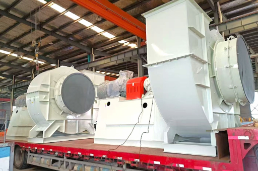
- Table of Contents
- Introduction to Induced Draft Fan Impeller Balancing
- Understanding the 1450-2900 RPM Operating Range
- Why Dynamic Balancing is Critical for ID Fans
- Pre-Balancing Inspection and Preparation
- Dynamic Balancing Adjustment Procedures
- Testing Protocols for Validation
- Common Challenges and Solutions
- Frequently Asked Questions (FAQ)
- Conclusion: Best Practices for Long-Term Fan Reliability
Precision Dynamic Balancing of 1450-2900 RPM Induced Draft Fan Impellers: Testing Procedures, Adjustment Techniques, and Performance Optimization
Table of Contents
- Introduction to Induced Draft Fan Impeller Balancing
- Understanding the 1450-2900 RPM Operating Range
- Why Dynamic Balancing is Critical for ID Fans
- Pre-Balancing Inspection and Preparation
- Dynamic Balancing Adjustment Procedures
- Testing Protocols for Validation
- Common Challenges and Solutions
- Frequently Asked Questions (FAQ)
- Conclusion: Best Practices for Long-Term Fan Reliability
Introduction to Induced Draft Fan Impeller Balancing
Induced draft (ID) fans are essential components in industrial processes such as power generation, cement production, and chemical processing. These fans operate by drawing combustion gases or process air through a system, creating negative pressure. The impeller, often large and heavy, rotates at speeds ranging from 1450 to 2900 RPM, making it susceptible to imbalances that can compromise performance and safety.
Dynamic balancing is the process of correcting mass distribution in a rotating component so that vibration levels remain within acceptable limits. For ID fan impellers, imbalance can arise from wear, erosion, material buildup, manufacturing tolerances, or damage. Without proper balancing, excessive vibration leads to bearing failure, shaft fatigue, coupling damage, and even catastrophic structural failure.
This article provides a comprehensive guide to dynamic balancing adjustment and testing for ID fan impellers operating in the 1450-2900 RPM range. The content is based on proven industrial practices and SEO-optimized for engineers, maintenance professionals, and plant operators seeking reliable information.
Understanding the 1450-2900 RPM Operating Range
The speed range of 1450 to 2900 RPM corresponds to medium-to-high rotational velocities typical of induced draft fans in many industrial settings. At these speeds, even small imbalances produce significant centrifugal forces. For example, a 1-gram imbalance at 2900 RPM generates a force equivalent to approximately 80 grams (0.78 N) acting on the bearing system. Over time, this force accelerates wear and reduces equipment lifespan.
Why this range matters:
- Resonance risk: Many fan support structures and foundations have natural frequencies within or near this speed range. Balancing minimizes the risk of exciting these resonances.
- ISO balance grades: For rigid rotors in this speed range, ISO 1940-1 typically recommends balance quality grade G6.3 or G2.5. Achieving these grades requires precise measurement and correction.
- Thermal effects: ID fans handle hot gases, often exceeding 150°C. Thermal expansion can alter balance state, so adjustments must account for operating conditions.
Understanding the relationship between speed, mass, and centrifugal force is fundamental to selecting proper balancing equipment and correction methods.
Why Dynamic Balancing is Critical for ID Fans
Induced draft fans are subject to harsh operating environments. Fly ash, dust, and corrosive gases accumulate on impeller blades unevenly. Over time, this material buildup creates imbalance that grows progressively worse. Additionally, blade erosion from particle impact removes material asymmetrically, further worsening the condition.
Consequences of ignoring imbalance:
- Bearing overheating and premature failure: Vibration transmits directly to bearings, increasing friction and heat generation.
- Shaft and coupling fatigue: Cyclic stresses cause metal fatigue, leading to cracks or breakage.
- Increased energy consumption: An unbalanced impeller requires more power to maintain speed, raising operational costs.
- Unplanned downtime: Emergency repairs are costly and disrupt production schedules.
Regular dynamic balancing adjustment and testing ensure the impeller operates within acceptable vibration limits, extending equipment life and reducing maintenance expenses. For fans operating at 1450-2900 RPM, balancing intervals typically range from 6 to 12 months, depending on operating conditions.
Pre-Balancing Inspection and Preparation
Before conducting any balancing adjustment, a thorough inspection is essential. Attempting to balance a damaged or heavily fouled impeller yields poor results and wastes time.
1 Visual Inspection Checklist
- Blade condition: Check for cracks, deformation, or missing sections. Repair or replace damaged blades before balancing.
- Material buildup: Remove any accumulated deposits using appropriate cleaning methods (e.g., water washing, chemical cleaning, or abrasive blasting).
- Weld integrity: Inspect all welds connecting blades to the hub or shroud. Cracks can propagate under dynamic loads.
- Hub and shaft fit: Ensure the impeller is securely mounted and centered on the shaft. Looseness mimics imbalance.
2 Equipment Preparation
- Balancing machine: Use a rigid or flexible rotor balancing machine capable of measuring both magnitude and phase angle. Portable field balancers are common for large ID fans.
- Vibration sensors: Accelerometers with a frequency range of at least 10-1000 Hz and sensitivity of 100 mV/g are suitable. Mount sensors on bearing housings in radial and axial directions.
- Tachometer: A laser or reflective tape sensor provides accurate RPM measurement and phase reference.
- Weight system: Pre-weighed correction weights (stainless steel or lead) in various sizes. Use magnetic or welded attachment methods as appropriate.
3 Initial Vibration Survey
Run the fan at its normal operating speed (typically 1450, 1750, or 2900 RPM) and record baseline vibration levels. Measure both displacement (mil or microns) and velocity (mm/s or in/s) at each bearing. Compare results with ISO 10816-3 limits for industrial fans. If vibration exceeds 11 mm/s (RMS) for rigid mounting, immediate balancing is required.
Dynamic Balancing Adjustment Procedures
Dynamic balancing of an ID fan impeller involves adding correction mass at precise angular locations to cancel the unbalanced force. The process follows the two-plane balancing method for most large impellers, as imbalance typically exists in two planes (e.g., at the hub and shroud).
1 Single-Plane vs. Two-Plane Balancing
- Single-plane: Suitable for narrow rotors (width-to-diameter ratio < 0.5). Corrects static imbalance only.
- Two-plane: Required for typical ID fan impellers. Corrects both static and couple imbalance. Most industrial fans need two-plane balancing for optimal results.
2 Step-by-Step Adjustment Process
Step 1: Install sensors and tachometer Mount accelerometers on both bearing housings. Place a reflective marker on the shaft or coupling for phase reference. Ensure the tachometer beam hits the marker consistently.
Step 2: Collect baseline data Run the fan at normal speed. Record vibration amplitude and phase angle for each bearing plane. Use a fast Fourier transform (FFT) analyzer to identify the 1X RPM component, which dominates in imbalance conditions.
Step 3: Add trial weights Select a trial weight (e.g., 10-30 grams, depending on impeller size). Attach it at a known radius on the impeller, typically on the hub or shroud ring. Document the angular position relative to the tachometer marker.
Step 4: Run and record Operate the fan again with the trial weight installed. Record the new vibration amplitude and phase for both planes. The change in vibration vector reveals the sensitivity of the system to the trial mass.
Step 5: Calculate correction Using vector mathematics (or balancing software), determine the required correction mass and angular location for each plane. The goal is to cancel the original imbalance vector with the correction vector.
Step 6: Apply correction weights Attach correction weights at the calculated positions. For permanent correction, weld the weights securely to the impeller structure. For temporary adjustments, use bolted or magnetic weights.
Step 7: Verify Run the fan again and measure vibration levels. If the results are within acceptable limits (typically < 2.5 mm/s RMS for G2.5 grade), the balancing is complete. If not, iterate with additional corrections.
3 Special Considerations for 1450-2900 RPM
- Soft foot and foundation issues: At higher speeds, even slight misalignment or foundation looseness can mask or amplify imbalance. Check these before balancing.
- Temperature effects: If the fan operates at elevated temperatures, perform balancing after the fan reaches thermal steady state. Balance changes as components expand.
- Multiple resonance: Ensure the balancing speed is not near a structural resonance. If resonance is present, consider adding damping or stiffening before balancing.
Testing Protocols for Validation
After correction, thorough testing confirms the impeller meets balance specifications. Testing should include:
1 Steady-State Vibration Measurement
- Measure at the fan bearings (drive and non-drive ends) in three orthogonal directions: radial vertical, radial horizontal, and axial.
- Acceptable limits per ISO 10816-3 for rigid fans: vibration velocity ≤ 4.5 mm/s (RMS) for "good" condition, ≤ 11 mm/s for "satisfactory". For critical applications, target ≤ 2.5 mm/s.
2 Slow Roll and Coast-Down Test
- Gradually reduce fan speed from 2900 RPM to zero. Record vibration amplitude across the speed range. A sudden spike indicates resonance. If the spike exceeds operational limits, additional corrective action (e.g., mass tuning or structural modification) is required.
3 Load Variation Test
- If the fan uses a variable-speed drive, test at 1450, 1750, 2200, and 2900 RPM. Verify that balance remains consistent across the speed range. Imbalance forces scale with the square of speed, so a small imbalance at 2900 RPM can become significant at higher speeds.
4 Repeatability Check
- Remove and reinstall the correction weights to verify that the balance state is reproducible. This ensures the weight attachment method is reliable.
5 Documentation
- Record all baseline and final vibration data, trial weight details, correction weight locations, and test conditions. This documentation is valuable for future maintenance and trend analysis.
Common Challenges and Solutions
Challenge 1: Unstable Baseline Vibration
- Cause: Loose foundation bolts, bearing wear, or variable process conditions (e.g., gas density changes).
- Solution: Tighten all mounting hardware, replace worn bearings, and stabilize process conditions before balancing.
Challenge 2: Phase Angle Drift During Testing
- Cause: Speed instability, poor tachometer signal, or thermal expansion.
- Solution: Use a high-precision tachometer and allow the fan to reach thermal equilibrium. Ensure the tachometer marker is clean and reflective.
Challenge 3: Insufficient Correction Weight Capacity
- Cause: Limited space or structural limitations on weight attachment points.
- Solution: Use heavier materials (tungsten or lead) for the same volume, or redistribute existing mass by removing material from heavy spots.
Challenge 4: Resonance Interference
- Cause: The fan operating speed coincides with a natural frequency of the support structure.
- Solution: Perform a modal analysis to identify resonance frequencies. Consider adding mass or stiffness to shift the natural frequency away from operating speed. Alternatively, change the fan speed if variable-speed drive is available.
Frequently Asked Questions (FAQ)
Q1: How often should ID fan impellers be dynamically balanced? A: For continuous operation in clean environments, balancing every 12 months is sufficient. For dirty or erosive environments, quarterly or semi-annual balancing is recommended. Always balance after any blade repair, replacement, or significant cleaning.
Q2: Can I balance an impeller without removing it from the fan? A: Yes, field balancing is standard for large ID fans. Portable balancing systems with accelerometers and tachometers provide accurate results without disassembly. However, access to the impeller for weight attachment is required.
Q3: What is the difference between static and dynamic balancing? A: Static balancing corrects imbalance where the principal mass axis is parallel to the rotational axis but displaced. Dynamic balancing corrects both static imbalance and couple imbalance, where the mass axis is tilted. For fans operating above 1000 RPM, dynamic balancing is essential.
Q4: What vibration limits should I target for 2900 RPM fans? A: Per ISO 10816-3, for rigid fans (natural frequency above operating speed), target vibration velocity ≤ 2.5 mm/s (RMS) for new or newly balanced fans. For flexible fans, ≤ 4.5 mm/s is acceptable. The lower limit ensures longer bearing and shaft life.
Q5: Why does the balance change after the fan heats up? A: Thermal expansion alters the dimensions and stiffness of the impeller and shaft. Asymmetric heating from hot gas can also create temporary imbalances. Always perform final balancing at the normal operating temperature.
Q6: Can I use adhesive weights instead of welded ones? A: Adhesive weights are acceptable for temporary correction or low-speed applications. For 1450-2900 RPM fans, welded or bolted weights are strongly recommended to withstand centrifugal forces and thermal cycling.
Q7: What tools do I need for dynamic balancing? A: A portable balancing analyzer with FFT capability, two accelerometers, a tachometer, trial weights, correction weights, and welding equipment. Computer software for vector calculations simplifies the process.
Q8: How do I know if the vibration is caused by imbalance or misalignment? A: Imbalance typically produces high 1X RPM vibration in the radial direction. Misalignment produces high 1X and 2X RPM vibration in the axial and radial directions. Use phase analysis: imbalance shows in-phase vibration at both bearings; misalignment shows out-of-phase or axial dominance.
Conclusion: Best Practices for Long-Term Fan Reliability
Dynamic balancing adjustment and testing of induced draft fan impellers in the 1450-2900 RPM range is a critical maintenance activity that directly impacts equipment reliability, energy efficiency, and plant safety. The key takeaways from this guide include:
- Always start with a thorough inspection to eliminate mechanical defects before balancing.
- Use proper balancing techniques (two-plane for most ID fans) and high-quality instrumentation.
- Account for operating conditions such as temperature and speed variation.
- Follow industry standards (ISO 1940-1, ISO 10816-3) for acceptable balance grades and vibration limits.
- Document all results to enable trend analysis and predictive maintenance.
By implementing regular balancing programs and following the procedures outlined in this article, plant operators can reduce unplanned downtime, extend bearing and shaft life by 30-50%, and lower annual maintenance costs significantly. For fans operating in harsh environments, consider investing in online vibration monitoring systems that provide real-time imbalance detection and alerting.
Remember that balance is not a one-time event but a continuous process. As impellers wear, accumulate deposits, or undergo thermal cycling, periodic re-balancing ensures optimal performance. When performed correctly, dynamic balancing of your 1450-2900 RPM induced draft fan impeller becomes a straightforward, repeatable process that pays dividends in reliability and operational efficiency.
This article was developed by synthesizing industry best practices from mechanical engineering standards, field maintenance experience, and technical literature on fan dynamics. For further reading, consult ISO 1940-1:2003 (Mechanical vibration — Balance quality requirements for rotors in a constant rigid state) and ISO 10816-3:2009 (Mechanical vibration — Evaluation of machine vibration by measurements on non-rotating parts).





