
This article's table of contents introduction:
- Understanding the Specifications
- Role of an Induced Draught (ID) Fan
- Design and Operating Characteristics for such a Fan
- Typical Operating Context (Size of Plant)
- Common Issues with Large ID Fans (like TUV series)
- Summary Table for your Fan
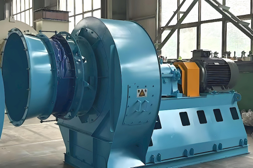
It looks like you are referring to a specific large-scale Induced Draft (ID) Fan used in a thermal power plant, with the model designation TUV and a flow capacity range of 53,650 to 1,050,000 m³/h.
Here is a detailed breakdown of what this specification typically means and the context of such a fan in a power plant.
Understanding the Specifications
- Model "TUV": This likely refers to a specific series or design standard from a manufacturer. While "TUV" is famously a German certification body (Technischer Überwachungsverein), in industrial fan naming, it often denotes a specific centrifugal fan design (e.g., a backward-curved or airfoil blade design). It could also be a part number for a fan from companies like TLT-Babcock, Howden, or similar OEMs.
- Flow Rate (Capacity): ( 53,650 \sim 1,050,000 \text{ m}^3/\text{h} )
- Minimum: 53,650 m³/h (approx. 895 m³/min or 31,600 CFM). This is likely the minimum stable operating point or turndown.
- Maximum: 1,050,000 m³/h (approx. 17,500 m³/min or 618,000 CFM). This is the full-load design flow.
- Context: This is a very large fan. A flow rate of 1,050,000 m³/h is typical for a 200 MW to 300 MW boiler unit's induced draft system.
Role of an Induced Draught (ID) Fan
In a thermal power plant (coal, biomass, or oil-fired), the ID fan is a critical component of the air and flue gas system. Its primary functions are:
- Maintain Slight Negative Pressure: It sits at the end of the system (after the electrostatic precipitator (ESP) and flue gas desulfurization (FGD) unit) and pulls the hot flue gases through the boiler, air heater, and pollution control equipment.
- Remove Combustion Products: It extracts the flue gases (CO₂, SOₓ, NOₓ, fly ash) from the boiler and pushes them up the chimney (stack).
- Safety: By maintaining negative pressure (draft) in the furnace, it prevents hot gases and flames from being forced out of the boiler casing into the plant environment.
Design and Operating Characteristics for such a Fan
Given the large flow range (20:1 turndown ratio) and the harsh environment, these fans are designed with specific features:
- Blade Type: Most large ID fans use Backward-Curved Airfoil (BCA) blades or Backward Inclined (BI) blades. Airfoil blades are more efficient but require clean gas (ESP must work well). For highly erosive or sticky ash (e.g., Indian coal), Radial Tip or Forward Curved blades might be used with wear liners.
- Speed: They are typically driven by a high-voltage motor (6.6 kV or 11 kV) via a coupling or gearbox.
- Flow Control:
- Inlet Guide Vanes (IGVs): The most common method. Variable vanes at the suction side of the fan control the flow by swirling the incoming air.
- VFD (Variable Frequency Drive): Increasingly common for better energy efficiency, though initial cost is high for such large motors (often 2-5 MW).
- Material: The impeller and casing are made of abrasion-resistant steel (e.g., Hardox, Corten) or have wear-resistant linings because flue gas contains fly ash particles.
- Bearing & Cooling: Heavy-duty roller bearings with forced oil lubrication or water cooling to handle the high radial loads and high ambient temperatures within the fan house.
- Vibration Monitoring: Continuous vibration probes are mandatory due to the massive rotating mass and the risk of imbalance from ash deposits.
Typical Operating Context (Size of Plant)
- Scenario A (Peak): 1,050,000 m³/h @ 250-300 °C.
- Likely used in a 250 MW - 300 MW unit.
- The fan would have a pressure rise of approximately 300-500 mmWG (millimeters of water gauge).
- Scenario B (Base Load / Turn Down): 53,650 m³/h.
This is the flow rate during low-load operation (e.g., 30% of capacity) or commissioning/start-up. Fans cannot run below a certain minimum flow without surging or stalling.
Common Issues with Large ID Fans (like TUV series)
- Wear (Erosion): The biggest killer. Fly ash particles erode the blade leading edges and tips.
- Imbalance: Caused by uneven ash deposition on blades or erosion.
- Vibration: Due to imbalance, bearing failure, or structural resonance.
- Surging: If the system resistance is too high (e.g., ESP or duct blockage) and the fan is throttled back too much.
- High Power Consumption: ID fans are one of the largest auxiliary power consumers in a plant (often 3-5% of total plant output).
Summary Table for your Fan
| Parameter | Value / Interpretation |
|---|---|
| Model | TUV (Likely centrifugal, backward-curved airfoil) |
| Flow Range | 53,650 – 1,050,000 m³/h |
| Function | Induced Draught (removes flue gas) |
| Typical Plant Size | 200 MW – 300 MW Thermal Unit |
| Expected Pressure | 300 – 500 mmWG (or 3-5 kPa) |
| Drive | High-voltage motor (generally fixed speed with IGVs or VFD) |
If you need specific information (e.g., exact motor power, pressure rating, or manufacturer's contact), please provide the full manufacturer name or the exact model number (e.g., TUV-20/18). For operational troubleshooting (e.g., high vibration or low flow), you would need to check the motor current, IGV angle, and flue gas temperature.





