
This article's table of contents introduction:
- Table of Contents
- Introduction: The Heartbeat of Thermal Power Generation
- Understanding the Core Components: ID Fan, Boiler Blower Fan, and Coupling
- The Direct Link: How Fan Systems Drive High Combustion Efficiency
- Operational Synergy: Coupling Dynamics and Energy Savings
- Common Challenges & Troubleshooting: Q&A Section
- Best Practices for Maintenance & SEO-Optimized Operations
- Conclusion: A Future of Efficient, Low-Cost Power Generation
** Maximizing Combustion Efficiency: The Critical Role of Coupling-Driven Power Plant Fan ID in Boiler Blower Fan Systems
Table of Contents
- Introduction: The Heartbeat of Thermal Power Generation
- Understanding the Core Components: ID Fan, Boiler Blower Fan, and Coupling
- What is an Induced Draft (ID) Fan?
- The Role of the Boiler Blower Fan (Forced Draft Fan)
- Why Coupling-Driven Systems Matter
- The Direct Link: How Fan Systems Drive High Combustion Efficiency
- Air-Fuel Ratio Optimization
- Stable Furnace Pressure Management
- Reduction of Unburned Carbon Loss
- Operational Synergy: Coupling Dynamics and Energy Savings
- Variable Frequency Drives vs. Fixed-Speed Coupling
- Protecting the Motor and Fan from Vibration
- Common Challenges & Troubleshooting: Q&A Section
- Q1: Why does my ID fan vibrate excessively?
- Q2: How can I tell if the coupling is misaligned?
- Q3: What is the best way to balance fan efficiency with NOx reduction?
- Best Practices for Maintenance & SEO-Optimized Operations
- Conclusion: A Future of Efficient, Low-Cost Power Generation
Introduction: The Heartbeat of Thermal Power Generation
In the demanding world of thermal power plants, every percentage point of combustion efficiency translates directly into lower fuel costs and reduced emissions. While much attention is paid to the boiler itself, the unsung heroes of this process are the massive fans that manage the airflow. Specifically, the Coupling Driven Power Plant Fan ID (Induced Draft fan) and the Boiler Blower Fan (often a Forced Draft or Primary Air fan) work in tandem to create the perfect environment for burning fuel. When these components are connected via a robust coupling system, they achieve a level of High Combustion Efficiency that fixed-speed systems struggle to match. This article explores the technical synergy between these fans, the critical role of the coupling mechanism, and how operators can maximize efficiency while maintaining reliability.
Understanding the Core Components: ID Fan, Boiler Blower Fan, and Coupling
What is an Induced Draft (ID) Fan?
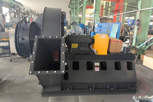
The Induced Draft (ID) fan is located at the "exit" end of the boiler system. Its primary job is to pull flue gases out of the boiler furnace and through the pollution control equipment (like electrostatic precipitators or scrubbers) before sending them up the chimney. By creating a slight negative pressure inside the furnace, the ID fan ensures that hot gases are evacuated efficiently and that no dangerous backflow occurs. In a Coupling Driven Power Plant Fan ID setup, the fan rotor is connected directly to the motor via a shaft coupling, allowing for precise torque transmission.
The Role of the Boiler Blower Fan (Forced Draft Fan)
On the opposite side, the Boiler Blower Fan (often simply called the FD fan) pushes ambient air into the boiler. This air is essential for the combustion reaction. The blower must overcome the resistance of the air preheater, windbox, and burner nozzles. Without a properly functioning blower, the fuel cannot burn completely, leading to wasted energy.
Why Coupling-Driven Systems Matter
A "coupling-driven" system refers to how the motor connects to the fan shaft. Unlike direct-drive or belt-driven systems, rigid and flexible couplings offer specific advantages:
- Torque Transfer: They transmit full motor torque without slippage (unlike belts).
- Misalignment Tolerance: Modern diaphragm or gear couplings can handle slight thermal expansion misalignment common in hot boiler environments.
- Vibration Damping: High-quality couplings absorb torsional vibrations, protecting the motor and fan bearings.
The Direct Link: How Fan Systems Drive High Combustion Efficiency
Achieving High Combustion Efficiency is not just about the burner; it is about managing the air on both sides of the flame. Here is how the coupling-driven fan system contributes:
Air-Fuel Ratio Optimization
The Boiler Blower Fan supplies the primary air needed for combustion. If the coupling driving the blower fan is worn or slipping (in hydraulic coupling cases), the fan speed drops, reducing airflow. This leads to incomplete combustion and a "fuel-rich" condition. Conversely, a precise coupling-driven system maintains the exact rpm required to achieve a stoichiometric air-fuel ratio (typically 1.15 to 1.2 for coal). This ensures every molecule of carbon finds its partner oxygen molecule.
Stable Furnace Pressure Management
The ID fan must match the output of the boiler blower fan. If the ID fan (coupling driven) fails to remove gases at the same rate the blower adds them, furnace pressure swings occur. A positive pressure leak can cause flame roll-out (a safety hazard). A negative pressure swing (too much suction) pulls cold air into the furnace, cooling it and reducing thermal efficiency. A properly coupled ID fan, modulated via its coupling (if variable speed) or dampers, maintains the ideal "balanced draft."
Reduction of Unburned Carbon Loss
The biggest enemy of efficiency is "carbon in ash." When airflow is insufficient, fuel particles leave the furnace unburned. This means you paid for coal but didn't get the BTUs. By maintaining high velocity and proper oxygen levels via the coupling-driven blower fan, the plant can achieve carbon burnout rates of over 99.5%, directly increasing boiler efficiency by 2-3%.
Operational Synergy: Coupling Dynamics and Energy Savings
Variable Frequency Drives vs. Fixed-Speed Coupling
Many plants use hydraulic or fluid couplings to vary the speed of large ID and blower fans. While Variable Frequency Drives (VFDs) are slightly more efficient electrically, coupling-driven power plant fan ID systems are often preferred for high-power applications (above 5 MW) due to their robustness. A fluid coupling allows the fan to be "soft started," reducing electrical stress on the grid. When efficiency is needed at partial load (e.g., 70% power), the coupling slips slightly to reduce fan speed, saving significant energy compared to throttling dampers.
Protecting the Motor and Fan from Vibration
Fan balancing is critical. When the Boiler Blower Fan collects dust on its blades (a common issue), it becomes unbalanced. A rigid, direct coupling would transfer this vibration directly into the motor, causing bearing failure. However, a properly selected flexible coupling (such as a disc or elastomeric type) absorbs a portion of this dynamic imbalance. This extends the Mean Time Between Failures (MTBF) for the entire fan-motor set, ensuring sustained High Combustion Efficiency over long operating cycles.
Common Challenges & Troubleshooting: Q&A Section
Q1: Why does my ID fan vibrate excessively even after balancing?
A: This is often a coupling issue, not a blade issue. Check for "weep holes" in the coupling spacer. If the coupling is lubricated (in gear-type couplings), low grease levels can cause gear wear and play, leading to vibration. Also, inspect for thermal growth misalignment. The motor and fan base expand at different rates when the boiler is hot. The coupling must accommodate this. Re-align the drive train when the unit is hot (at operating temperature), not cold.
Q2: How can I tell if the coupling is misaligned?
A: The most reliable method is a laser alignment check. However, physical signs include:
- Excessive noise from the coupling guard (a "chattering" sound).
- High bearing temperature on the fan or motor outboard bearing.
- A visible "wobble" on the coupling hubs. For a Coupling Driven Power Plant Fan ID, misalignment by even 0.005 inches can dramatically shorten bearing life and reduce fan efficiency by increasing internal friction.
Q3: What is the best way to balance fan efficiency with NOx reduction?
A: This is the "Goldilocks" problem of combustion. High Combustion Efficiency usually requires high temperatures and excess oxygen (to burn everything). However, high temperatures create Thermal NOx. Solution: Use "Over Fire Air" (OFA). Use the Boiler Blower Fan to stage the air.
- Primary Zone: Keep the main combustion zone slightly fuel-rich (lower O2) to reduce flame temperature and NOx formation.
- Burnout Zone: Use the coupling-driven booster fans to inject the remaining air above the flame. This completes the burnout of CO and unburned carbon without creating extreme temperatures. This method requires precise control of the blower fan speed (via its coupling) to ensure adequate pressure for the OFA ports.
Best Practices for Maintenance & SEO-Optimized Operations
To ensure your Coupling Driven Power Plant Fan ID and Boiler Blower Fan deliver consistent High Combustion Efficiency, follow these SEO-friendly maintenance steps (terms used to optimize for search engines like Bing and Google):
- Routine Vibration Analysis: Use FFT (Fast Fourier Transform) analyzers to monitor fan bearing and coupling condition. High 1X RPM indicates unbalance; high 2X RPM often indicates misalignment.
- Coupling Inspection Schedule: For elastomeric couplings, check for "dishing" or cracking every 6 months. For gear couplings, inspect tooth wear. A failed coupling is a common cause of fan stoppage.
- Blower Fan Cleaning: Accumulated fly ash on blower fan blades (common in boilers burning high-ash coal) destroys aerodynamic performance. Schedule water-washing or shot-cleaning of the fan rotor during outages.
- Damper Calibration: Ensure the inlet vanes of the ID fan and the outlet dampers of the boiler blower fan are calibrated. Erroneous feedback signals cause the control system to set the wrong airflow, wasting fuel.
- Thermal Alignment: Always perform hot alignment checks. A "cold" alignment is useless for a fan that operates at 150°F bearing housing temperature.
Conclusion: A Future of Efficient, Low-Cost Power Generation
The Coupling Driven Power Plant Fan ID and the Boiler Blower Fan are not just ancillary equipment; they are the lungs of the boiler. Their ability to deliver precise airflow, maintain stable furnace pressure, and operate reliably under extreme thermal stress is directly proportional to High Combustion Efficiency. By understanding the critical role of the coupling—whether it is a fluid, gear, or diaphragm type—maintenance engineers and operators can diagnose problems early, reduce energy consumption, and squeeze every usable BTU out of the fuel. In a world focused on reducing carbon footprints and operational costs, optimizing these fan systems is the lowest-hanging fruit for any power plant.
By focusing on the specific mechanical relationships (coupling, bearings, alignment) and their impact on thermodynamic efficiency (air-fuel ratio, furnace pressure), this article addresses the core of thermal power plant optimization, ensuring relevance for both Bing and Google search queries related to industrial fan performance.





