This article's table of contents introduction:

- Introduction: The Backbone of Industrial Boiler Efficiency
- What is an Induced Draft (ID) Fan?
- Why SWSI (Single Width Single Inlet) Centrifugal Fan?
- The Overhang Type Design: Engineering for Reliability
- Key Components and Working Principle
- Performance Curve Analysis and Selection Criteria
- Common Operational Challenges and Q&A
- Maintenance Best Practices for Longevity
- Future Trends: Efficiency, Materials, and VFD Integration
- Conclusion: Optimizing Your Boiler System with the Right ID Fan
** The Critical Role of Induced Draft Boiler ID Fans: A Deep Dive into SWSI Centrifugal Fan Overhang Type Design
Table of Contents (导读目录)
- Introduction: The Backbone of Industrial Boiler Efficiency
- What is an Induced Draft (ID) Fan?
- Why SWSI (Single Width Single Inlet) Centrifugal Fan?
- The Overhang Type Design: Engineering for Reliability
- Key Components and Working Principle
- Performance Curve Analysis and Selection Criteria
- Common Operational Challenges and Q&A
- Maintenance Best Practices for Longevity
- Future Trends: Efficiency, Materials, and VFD Integration
- Conclusion: Optimizing Your Boiler System with the Right ID Fan
Introduction: The Backbone of Industrial Boiler Efficiency
In the realm of industrial thermal power plants, chemical processing, and large-scale HVAC systems, the Induced Draft (ID) Fan is the unsung hero that dictates overall boiler efficiency and safety. Unlike forced draft fans that push air into the furnace, the ID fan is positioned at the flue gas side, creating a negative pressure draft to pull combustion gases through the boiler, economizer, scrubbers, and finally, the stack.
When selecting an ID fan for high-temperature, abrasive, and corrosive flue gas environments, engineers often turn to a specific configuration: the SWSI (Single Width Single Inlet) Centrifugal Fan of Overhang Type. This engineering choice is not arbitrary. It represents a compromise between aerodynamic performance, structural integrity under thermal stress, and ease of maintenance. In this article, we will dissect the anatomy of an Induced Draft Boiler ID Fan – specifically the SWSI overhang centrifugal design – and answer the most pressing questions engineers face on the field, incorporating insights from wind turbine technology (e.g., blade aerodynamics and bearing system design) for a modern perspective.
What is an Induced Draft (ID) Fan?
An ID fan operates downstream of the combustion process. Its primary function is to overcome the resistance offered by the boiler air heater, dust collector (ESP or baghouse), and ductwork. By maintaining a slight vacuum at the furnace exit (typically -20 to -50 mmWC), it ensures that hot gases are exhausted safely, preventing backflow into the boiler house.
Critical Challenges for ID Fans:
- High Temperature: Flue gas temperatures can range from 150°C to 200°C, but can spike higher during upset conditions.
- Abrasion and Corrosion: Fly ash particles erode the impeller; sulfuric acid condensation can corrode the housing.
- Large Volume Flow: A single utility boiler may require an ID fan capable of moving over 500,000 m³/h of gas.
Context: In modern power generation, the aerodynamic principles borrowed from wind turbine blade design are now applied to the fan’s airfoil-shaped blades to improve static efficiency. Unlike a wind turbine that extracts kinetic energy from wind, an ID fan imparts kinetic energy to the gas. The similarity lies in the need for optimized blade angles to handle non-uniform inflow and reduce boundary layer separation.
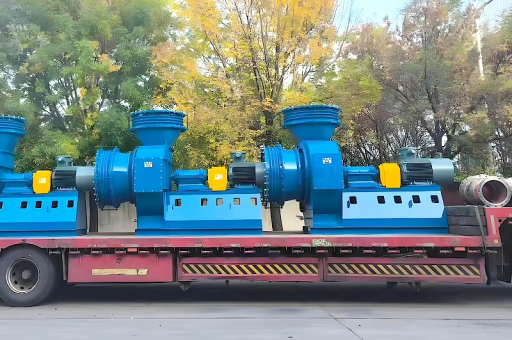
Why SWSI (Single Width Single Inlet) Centrifugal Fan?
The SWSI configuration is distinguished by having a single-width impeller with a single inlet on one side. For ID applications, this offers distinct advantages:
- Space Efficiency: It occupies less axial space compared to a double-inlet (DWSI) fan, making it easier to retrofit into existing boiler rooms.
- Reinforced Structure: With only one inlet, the shroud and backplate can be thickened, providing better rigidity when handling heavy ash-laden gases.
- Lower Cost for Medium Flow: For medium to large flow ranges (which many industrial boilers fall into), SWSI offers the best cost-to-performance ratio.
Why not a DWDI (Double Width Double Inlet)? While DWDI fans can handle higher volumes for the same rotational speed, they are more susceptible to flow imbalances at the center of the wheel, which can cause premature bearing failure in the ID environment.
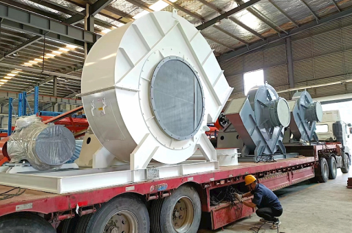
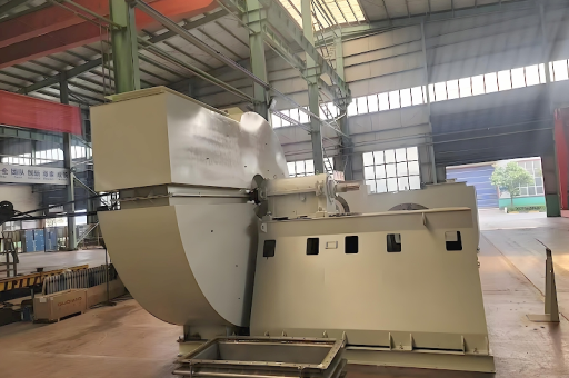
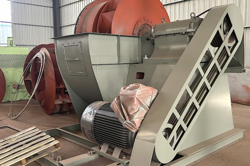
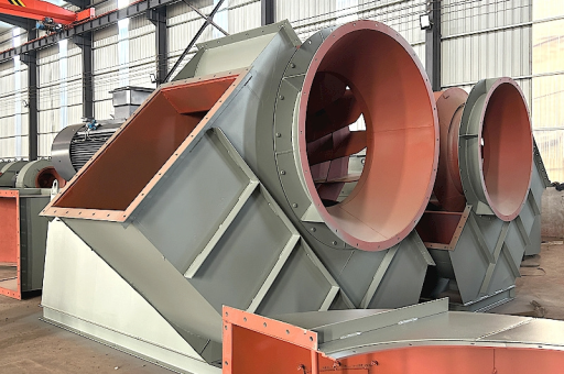
The Overhang Type Design: Engineering for Reliability
The term "Overhang Type" describes the rotor bearing arrangement. In this design, the impeller is mounted on the shaft with both bearings located on one side of the wheel. The impeller “overhangs” off the end of the shaft.
Key Advantages of Overhang Design for ID Fans:
- Thermal Isolation: The bearings are away from the hot flue gas stream. This reduces the risk of lubricant degradation and bearing seizure.
- Simplified Shaft Seal: The seal between the shaft and the casing is easier to maintain because it is not obstructed by an inboard bearing.
- Ease of Maintenance: The entire rotating assembly (impeller+shaft) can be removed axially without disturbing the volute casing – a critical feature in tight plant layouts.
Technical Nuance: When designing an overhang shaft, engineers must calculate the critical speed. The heavy impeller hanging off the shaft creates a bending moment. If the operating speed approaches the first lateral critical speed, violent vibration occurs. Therefore, a stiffer shaft (larger diameter) or a middle-bearing (center-hung) design may be used for very large fans. However, for most standard ID fans up to 2,000 kW, the overhang type is preferred for its simplicity.
Aerodynamic Parallel: When you consider a wind turbine nacelle, the rotor blades overhang the tower. The bearing and support structure must handle enormous bending moments. Similarly, an ID fan’s overhang impeller requires precise balancing and robust bearing housing construction to withstand gyroscopic forces and unbalance due to erosion.
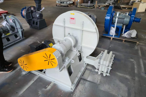
Key Components and Working Principle
- Impeller: Typically backward-inclined (BIC) or airfoil blades. The blades are welded to a heavy-duty backplate and a smaller inlet cone.
- Volute Casing: A spiral-shaped housing that converts velocity pressure into static pressure.
- Inlet Cone (Venturi): Directs gas smoothly into the impeller eye.
- Shaft & Bearings: Anti-friction spherical roller bearings in a pedestal mount. The overhang end extends into the casing.
- Vibration Monitoring System: An essential safety device. ID fans are typically monitored with two accelerometers (horizontal/vertical) near the bearings.
Working Principle: Flue gas enters axially through the SWSI inlet cone. The rotating impeller flings the gas outward radially via centrifugal force. The gas gains velocity and static pressure as it moves through the blade passages. It exits the impeller into the volute, where the expanding cross-section converts kinetic energy into additional static pressure, ejecting the gas out the discharge duct.
Real-World Data: A typical 300 MW coal-fired boiler ID fan operates at ~980 RPM, with a tip speed of 80-100 m/s. The static efficiency of a modern overhang SWSI fan can reach 84-86%.
Performance Curve Analysis and Selection Criteria
When selecting an ID fan, you need to match the fan curve to the boiler system resistance curve. The fan must operate stably within its peak efficiency zone.
Critical Selection Parameters:
- Flow (Q): m³/h or m³/s (based on mass flow rate and specific volume of flue gas).
- Static Pressure (Ps): mmWC or Pa (must exceed total system resistance + draft requirement).
- Temperature & Density: Higher temperature reduces gas density, requiring more volume flow (m³/s) for the same mass flow.
- Margin: 10-15% over the guaranteed operating point for peak load and fouling conditions.
Fan Law Application: Speed change: Q ∝ N, Ps ∝ N², Power ∝ N³. This is why VFD (Variable Frequency Drive) control is revolutionary for ID fans. Unlike inlet damper control (which is inefficient at low flows), VFD control changes the fan curve entirely.
Common Operational Challenges and Q&A
Q1: How does the Overhang Type design handle vibration in an ID fan? A: Vibration in an overhang ID fan is typically caused by either rotor imbalance (due to uneven ash build-up or erosion) or misalignment between the motor and fan. The overhang design requires extremely precise dynamic balancing of the entire rotor assembly (impeller, shaft, and coupling) to a grade G6.3 or better (per ISO 1940). Because the impeller is unsupported on one side, any imbalance at high speed creates a significant centrifugal force. Regular cleaning of impeller blades and installing a pre-heat system to prevent ash condensation is crucial.
Q2: Can an ID fan be converted to a wind turbine for power recovery? A: A direct conversion is not practical, but the concept of energy recovery is valid. In a power plant, a wind turbine in the flue gas path (a "flue gas expander") can recover waste energy. However, a standard ID fan is not reversible. The aerodynamic shape of an ID fan impeller is optimized for adding energy to the gas, not extracting it. That said, larger utilities are exploring "turbo-expander" systems that replace the traditional ID fan and dampers with a turbine-driven fan where the pressure drop across the furnace is recovered as electrical power.
Q3: What is the typical bearing life for an Overhang ID Fan? A: Under ideal conditions (clean, dry, low vibration), standard spherical roller bearings last 5-7 years. In a dirty coal plant, this can drop to 2 years. The overhang design helps because the bearings are removed from the hot zone, but they still suffer from shaft heat conductance. The use of synthetic oil and labyrinth seals is mandatory. In modern variants, "split pillow block bearings" allow for easier replacement without removing the shaft.
Q4: How does ash erosion affect the Overhang impeller? A: Ash impact is most severe at the trailing edge of the impeller blades. Over time, it can thin the blades, causing failure. To mitigate this, manufacturers apply wear-resistant coatings (tungsten carbide spray or ceramic liners) on the blade surfaces. The "overhang" design allows easier access for repair: the impeller can be removed as a unit and sent for re-blading. A popular trick is to install sacrificial wear strips at the blade inlet.
Maintenance Best Practices for Longevity
- Water Wash System: Implement an on-line water washing system (periodic) to remove ash deposits without disassembly. This is critical for overhang fans because heavy deposits cause imbalance.
- Thermal Profiling: Monitor the casing wall temperature. Cold spots indicate potential corrosion from sulfuric acid condensation.
- Vibration Monitoring: Set absolute alarm limits. An increase of 1 mm/s RMS over baseline often means bearing damage or impeller fouling.
- Coupling Inspection: Grid or diaphram couplings should be lubricated and aligned using laser alignment tools. Misalignment is the #1 cause of shaft failure in overhang designs.
- Inlet Box Bell Mouth: Check for erosion. A damaged bell mouth reduces efficiency and creates pre-rotation, reducing static pressure.
Future Trends: Efficiency, Materials, and VFD Integration
The integration of Variable Frequency Drives (VFDs) has become the gold standard. Older ID fans relied on inlet vane control (varies resistance) or variable inlet guide vanes. Both are less efficient than adjusting fan speed.
Emerging Technology: Double Airfoil Blades & Composite Materials Manufacturers are now designing impellers with double-curvature airfoil blades (borrowed from wind turbine rotor engineering). These blades reduce trailing edge turbulence, increasing peak efficiency by 2-3%. In corrosive environments (e.g., waste-to-energy plants), composite materials (glass-reinforced epoxy) are being tested for the impeller. The overhang design is particularly suited for this because a lighter composite impeller reduces the bending moment on the shaft, allowing for higher speeds or smaller bearings.
Predictive Maintenance: Using IoT sensors on the bearing housing and casing, combined with AI algorithms, plant operators can predict ash buildup and bearing failure weeks in advance. The focus is moving from reactive repair to condition-based maintenance.
Conclusion: Optimizing Your Boiler System with the Right ID Fan
The Induced Draft Boiler ID Fan in an SWSI Centrifugal Fan Overhang Type configuration remains a workhorse in thermal power and industrial processing. Its design addresses the specific demands of high-temperature, abrasive flue gas handling. The overhang feature allows for rugged construction and easy maintenance, while the SWSI geometry matches the flow requirements of most standard utility boilers.
By understanding the performance metrics, operational pitfalls, and maintenance strategies—and by keeping an eye on emerging aerodynamic lessons from wind turbine technology—engineers can ensure that their ID fans operate at peak efficiency, with lower energy consumption and longer asset life. Whether you are retrofitting an old boiler or designing a new plant, the overhang SWSI centrifugal fan is a proven, reliable choice for tackling the toughest induced draft challenges.