This article's table of contents introduction:

- Core Function in the Thermal Power Plant
- What "Single Suction" Means (Mechanical Configuration)
- Key Design Characteristics of a Single Suction ID Fan
- Why Choose a Single Suction Design?
- Operational Challenges & Solutions
- Control Mechanisms
- Summary Table: Single Suction vs. Double Suction ID Fan
- Conclusion
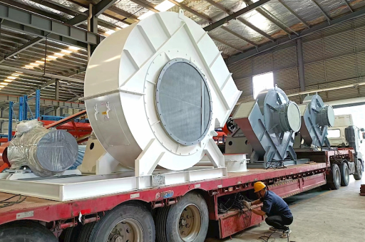
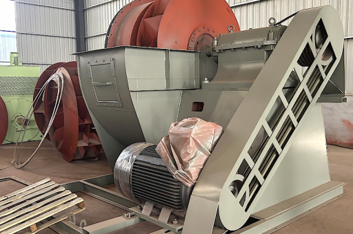
The High Air Flow Induced Draft (ID) Fan in a thermal power plant is a critical component of the boiler flue gas system. When specified as a Single Suction fan, it refers to the mechanical configuration of the impeller's air intake.
Here is a detailed breakdown of this specific equipment, its function, design, and operational context.
Core Function in the Thermal Power Plant
The ID fan’s primary job is to maintain a negative pressure (draft) in the furnace and the boiler flue gas path. It does this by pulling (inducing) the hot flue gases out of the boiler, through the air pollution control equipment (ESP, FGD), and up the chimney.
Critical Benefits of this Negative Pressure:
- Safety: Prevents hot flue gas and flame from leaking out of the boiler casing, protecting operators and equipment.
- Efficiency: Ensures proper air flow through the combustion zone for optimal fuel burning.
- System Flow: Overcomes the resistance of ductwork, air heaters, electrostatic precipitators (ESP), and flue gas desulfurization (FGD) systems.
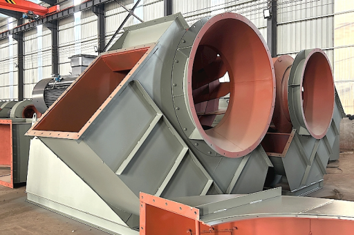
What "Single Suction" Means (Mechanical Configuration)
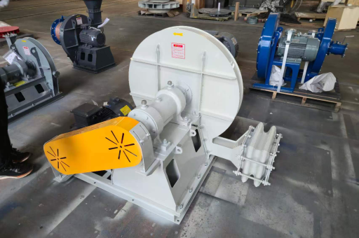
- Design: The fan has a single inlet on one side of the impeller. Air enters the fan axially from one direction only.
- Impeller: Typically a single-width, single-inlet (SWSI) impeller.
- Comparison with Double Suction: A double suction fan has two inlets (one on each side of the impeller), which balances axial thrust and allows for higher flow rates in a more compact size.
Key Design Characteristics of a Single Suction ID Fan
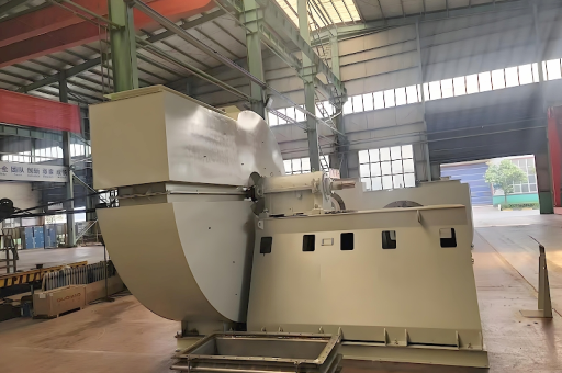
- High Flow, Low-to-Medium Pressure: ID fans are designed to move massive volumes of gas (millions of CFM) at a relatively low pressure differential (typically 20-40 inches of water gauge).
- Heavy-Duty Construction: They must handle hot (150°C to 180°C typical), dusty, and corrosive flue gases.
- Centrifugal Design: Almost all large ID fans are centrifugal fans. They use a rotating impeller to increase the velocity of the gas and then a volute casing to convert that velocity into pressure.
- Blade Type:
- Backward Curved / Backward Inclined: Most common. They are highly efficient, non-overloading (power draw peaks at a certain flow), and handle dust better than forward curved blades.
- Radial Blade: Used for very high dust loads or erosive environments. Less efficient but more robust.
- Bearings: Heavy-duty, often with water or oil cooling, and vibration monitoring. Since it's a single suction, the axial thrust is significant and must be handled by a thrust bearing.
Why Choose a Single Suction Design?
- Simpler Ductwork: The inlet ducting is simpler and requires less space than a double suction fan, which needs a Y-duct or a large plenum to feed both sides.
- Cost (for smaller units): For smaller capacity power plants or smaller units within a large plant, a single suction fan can be more economical.
- Maintenance Access: The non-drive end (inlet side) is fully accessible for inspection and maintenance of the impeller without disassembling the inlet ductwork on both sides.
Operational Challenges & Solutions
| Challenge | Impact on Single Suction ID Fan | Mitigation Strategy |
|---|---|---|
| High Temperature | Reduces material strength; risk of thermal expansion causing rubbing. | Use of alloy steels (e.g., Corten, SA-387); cooling air to shaft seals; thermal expansion joints in ducting. |
| Erosion (Fly Ash) | Wears down impeller blades and casing, causing imbalance and reduced efficiency. | Hard-facing (welding) on leading edges; replaceable wear liners; ceramic tiles in high-wear zones. |
| Corrosion | Caused by sulfur oxides (SOx) and water vapor (acid dew point). | Use of corrosion-resistant coatings (e.g., glass flake, epoxy) or high-alloy materials (e.g., Hastelloy). |
| Axial Thrust | Single suction creates a net axial force pushing the impeller toward the inlet. | Robust thrust bearing; balance holes in the impeller backplate (though this reduces efficiency slightly). |
| Vibration | Imbalance from erosion or dust buildup. | Continuous vibration monitoring (accelerometers); routine cleaning (e.g., water washing or compressed air during shutdowns). |
| Surge / Stall | Operating at very low flow rates can cause unstable flow and mechanical damage. | Proper control system (variable speed drives or variable inlet vanes) to keep fan in stable operating region. |
Control Mechanisms
To regulate the high air flow, the fan is controlled by either:
- Variable Frequency Drive (VFD): Most efficient. Changes the motor speed to match the required flow. Preferred for modern plants.
- Variable Inlet Vanes (VIV): Adjustable guide vanes at the fan inlet. They pre-swirl the air entering the impeller, reducing power consumption. Less efficient than VFDs but simpler for very large motors.
- Inlet Dampers / Louvers: Fixed or modulating dampers. Least efficient, as they simply add resistance.
Summary Table: Single Suction vs. Double Suction ID Fan
| Feature | Single Suction | Double Suction |
|---|---|---|
| Flow Capacity | Moderate to High | Very High |
| Pressure Capability | Moderate | Moderate |
| Space Required | Less (simpler inlet duct) | More (requires Y-duct or large plenum) |
| Axial Thrust | High | Balanced (low) |
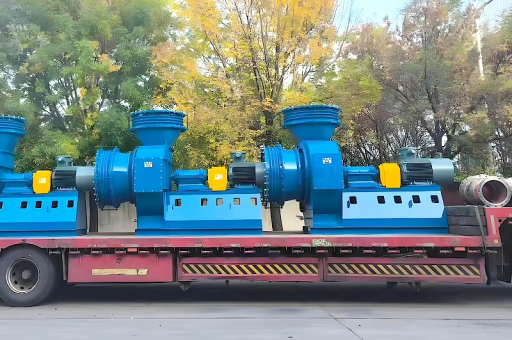
| Common Application | Medium-sized utility boilers (100-300 MW) | Large utility boilers (>300 MW) |
| Cost | Lower for its given size | Higher |
Conclusion
The High Air Flow Induced Draft Fan in Single Suction configuration is a workhorse in medium-to-large capacity thermal power plants. Its design balances the need for massive gas volume handling with the cost and space constraints of simpler inlet ductwork. The key to its longevity and reliability lies in robust materials to combat erosion and corrosion, effective bearing systems to manage axial thrust, and a proper control scheme (VFD or VIV) to prevent surge and maximize efficiency.