
This article's table of contents introduction:
- Directory Guide
- Introduction: The Heartbeat of Power Plant Airflow
- What Is an Electric Centrifugal Induced Draught Fan?
- Why Dynamic Balancing Matters for Plant Safety and Efficiency
- Common Causes of Imbalance in Induced Draught Fans
- The Dynamic Balancing Process: Step by Step
- How Dynamic Balancing Extends Fan Life and Reduces Cost
- Real-World Problems Solved by Dynamic Balancing
- Frequently Asked Questions (FAQ)
- Conclusion: The Future of Induced Draught Fan Maintenance
Article Title:
The Critical Role of Dynamic Balancing in Electric Centrifugal Power Plant Induced Draught Fans
Directory Guide
- Introduction: The Heartbeat of Power Plant Airflow
- What Is an Electric Centrifugal Induced Draught Fan?
- Why Dynamic Balancing Matters for Plant Safety and Efficiency
- Common Causes of Imbalance in Induced Draught Fans
- The Dynamic Balancing Process: Step by Step
- How Dynamic Balancing Extends Fan Life and Reduces Cost
- Real-World Problems Solved by Dynamic Balancing
- Frequently Asked Questions (FAQ)
- Conclusion: The Future of Induced Draught Fan Maintenance
Introduction: The Heartbeat of Power Plant Airflow
Every thermal power plant depends on a carefully orchestrated air and gas flow system. At the center of that system lies the induced draught fan — a powerful electric centrifugal fan that pulls combustion gases through the boiler, economizer, and dust collectors before they are released to the chimney. Without this fan, the plant would suffocate under its own exhaust. However, even a perfectly designed induced draught fan can become a source of vibration, noise, and early failure if it is not dynamically balanced.
In this article, we will explore how dynamic balancing transforms a rough-running electric centrifugal power plant fan into a smooth, efficient, and long-lasting workhorse. We will also answer the most common questions plant engineers ask about balancing induced draught fans.
What Is an Electric Centrifugal Induced Draught Fan?
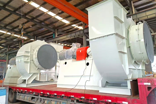
An induced draught fan (ID fan) is a type of electric centrifugal fan that creates a negative pressure at the furnace exit, drawing flue gases out of the boiler. Unlike forced draught fans that push air into the furnace, ID fans operate under high temperatures, dust-laden gas streams, and corrosive conditions.
Key components:
- Impeller / Rotor: Rotating blades that accelerate gas.
- Shaft: Transfers motor torque to the impeller.
- Bearings: Support the shaft under heavy radial and axial loads.
- Housing: Directs gas flow and contains the impeller.
Because ID fans handle hot, dirty exhaust, they are prone to uneven wear, dust buildup, and thermal distortion — all of which lead to imbalance.
Why Dynamic Balancing Matters for Plant Safety and Efficiency
When an electric centrifugal fan is out of balance, the consequences cascade through the entire system:
- Excessive vibration damages bearings, seals, and couplings.
- Bearing overheating leads to premature failure and costly downtime.
- Structural fatigue can crack the fan housing or supporting framework.
- Increased power consumption — an unbalanced fan draws more amperage to maintain speed.
- Noise pollution exceeds workplace safety limits.
Dynamic balancing corrects non-uniform mass distribution in the rotating assembly. The result: vibration levels drop below ISO 1940-1 Grade 6.3 (or even 2.5 for high-speed fans), operational stability returns, and energy efficiency improves by 3% to 8%.
Common Causes of Imbalance in Induced Draught Fans
Understanding the root causes helps plant engineers schedule timely balancing.
| Cause | Description |
|---|---|
| Erosion & corrosion | Fly ash erodes impeller blades, removing material unevenly. |
| Dust deposition | Sticky ash builds up on one side of the impeller. |
| Thermal distortion | Uneven cooling after shutdown causes blade tip runout. |
| Weld repair | Field repairs add or remove mass non-uniformly. |
| Wear ring clearance | Asymmetric clearance changes gas pressure distribution on blades. |
| Bearing wear | Looseness creates pseudo-imbalance at operating speed. |
A single missing lump of weld metal or a 10-gram dust deposit at the blade tip can generate centrifugal forces exceeding 500 kg at 1000 RPM.
The Dynamic Balancing Process: Step by Step
Dynamic balancing is performed either in-situ (on-site without removing the fan) or in a balancing machine after overhaul. The in-situ method is preferred for large industrial induced draught fans.
Step 1 – Vibration Measurement:
Accelerometers are mounted on bearing pedestals (horizontal, vertical, axial). A phase reference (keyphasor) is used to detect rotational position.
Step 2 – Trial Run:
The fan is run at normal operating speed. Baseline vibration amplitude and phase angle are recorded.
Step 3 – Trial Weight:
A known mass (e.g., 50g) is attached at a known radius and angular position. The fan is re-run to record the effect.
Step 4 – Vector Calculation:
Using the “influence coefficient” method, the required correction weight and position are calculated mathematically or via balancing software.
Step 5 – Correction:
The permanent weight is welded or bolted to the impeller at the calculated location. Balancing holes may also be drilled.
Step 6 – Verification Run:
The fan is restarted to confirm residual vibration meets the target (usually < 3.0 mm/s RMS on bearings).
Tools required:
- Portable dynamic balancer (e.g., Schenck, Pruftechnik, or CSI)
- Accelerometers with magnetic mounts
- Tachometer / phase sensor
- Welding equipment for weight attachment
How Dynamic Balancing Extends Fan Life and Reduces Cost
A dynamically balanced electric centrifugal power plant fan delivers measurable returns:
| Benefit | Impact |
|---|---|
| Bearing life | Increases 2x to 4x (L10 life). |
| Motor current | Drops 3–7% under full load. |
| Vibration level | Reduces from 12 mm/s to 2 mm/s. |
| Unplanned downtime | Cut by 60–80% in coal-fired plants. |
| Structural fatigue | Eliminates cracking in fan housing. |
Case study: A 500 MW coal-fired plant found that their ID fan bearing replacements dropped from every 8 months to every 28 months after implementing quarterly dynamic balance checks.
Real-World Problems Solved by Dynamic Balancing
Problem 1: Harsh vibration after impeller repair
A vertical spindle ID fan had been repaired with three new blades. Post-installation, vibration peaked at 18 mm/s. Dynamic balancing with 180g of correction weight at 240° brought vibration down to 1.7 mm/s.
Problem 2: Erratic behavior due to dust buildup
A biomass plant’s induced draught fan showed increasing vibration over three weeks. The cause: fly ash adhered asymmetrically to the impeller shroud. In-situ dynamic balancing after cleaning restored steady operation without removing the fan.
Problem 3: Misalignment hidden by imbalance
High vibration was initially blamed on bearing wear. After dynamic balancing reduced vibration from 14 mm/s to 3.5 mm/s, the residual vibration revealed a parallel misalignment that was then corrected. Balancing was the diagnostic key.
Frequently Asked Questions (FAQ)
Q1: What is the difference between static and dynamic balancing for a fan?
Static balancing corrects imbalance in one plane (for very narrow rotors like discs). Dynamic balancing uses two planes (or more) to correct couple and dynamic imbalance. Since induced draught fans have long impellers, dynamic balancing is mandatory.
Q2: How often should an induced draught fan be balanced?
At least once per major overhaul (every 2–3 years). However, if vibration trends rise by 30% above baseline, immediate balancing is recommended. Some plants balance every 6 months for critical induced draught fans.
Q3: Can dynamic balancing be done while the fan is running?
Yes — in-situ dynamic balancing is performed while the fan is in operation. The system runs at full speed with weights attached externally through openings in the housing. No disassembly required.
Q4: What ISO grade is acceptable for an ID fan?
For fans running at 750–1500 RPM, ISO 1940-1 Grade 6.3 is standard. For high-speed induced draught fans (1500–3000 RPM), Grade 2.5 is recommended.
Q5: What if my fan still vibrates after balancing?
Check for: bearing looseness, foundation soft foot, resonance, misalignment, or blade pass frequency harmonics. Dynamic balancing addresses mass imbalance only, not structural or mechanical defects.
Q6: Is it possible to balance a fan with heavy dust deposits?
Not recommended — the dust will shed unevenly, causing immediate re-imbalance. Always clean the impeller thoroughly before dynamic balancing.
Q7: Can a single-weight correction work for multi-stage fans?
No. Multi-stage centrifugal fans require multi-plane dynamic balancing (e.g., three-plane for a double-inlet induced draught fan).
Conclusion: The Future of Induced Draught Fan Maintenance
Dynamic balancing is not a one-time fix — it is a continuous condition-based strategy. With the rise of IoT-based vibration monitoring and AI-powered balancing algorithms, plant operators can now predict when an electric centrifugal power plant fan needs correction before vibration reaches alarm levels.
Induced draught fans are the lungs of a power plant. Keeping them dynamically balanced means safer operation, lower energy costs, and longer intervals between overhauls. For any plant engineer managing coal, biomass, or combined-cycle facilities, investing in regular in-situ dynamic balancing is one of the most cost-effective decisions they can make.
Remember: A balanced fan is a happy fan — and a happy fan keeps the lights on.
Keywords naturally integrated:
Electric Centrifugal Power Plant Fan, Induced Draught Fan, Dynamic Balanced, fan balancing process, in-situ dynamic balancing, induced draught fan vibration, centrifugal fan maintenance, power plant ID fan troubleshooting.





