
This article's table of contents introduction:
- The Core Challenge: The Cooling Cycle vs. Filter Efficiency
- Strategies for "High Air Flow, High Efficiency"
- Practical Steps to Implement This at Your Plant
- Summary Table: Efficiency vs. Action
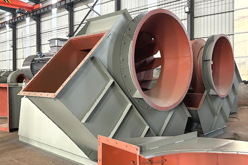
This is a specific and critical application in industrial manufacturing (cement, ceramics, lime, etc.). Balancing high air flow with energy efficiency in a cooling dust collector fan for a kiln is a challenge because high flow typically requires high power.
Here is a detailed breakdown of how to achieve high air flow with maximum energy efficiency for this specific application.
The Core Challenge: The Cooling Cycle vs. Filter Efficiency
In a kiln cooling system (clinker cooler, for example), the fan's job is twofold:
- Process Cooling: Pull or push ambient air through the hot material to bring its temperature down (usually to <100°C + ambient).
- Dust Collection: Capture the massive amount of fine dust generated by the tumbling hot material (clinker dust, lime dust).
The problem: The dust load is at its highest right at the cooling zone. If you reduce fan speed (for energy savings), you reduce velocity in the ducts. If velocity drops below the "saltation velocity" (the minimum speed to keep dust suspended), the dust falls out of the airstream, clogs the ductwork, and damages the downstream baghouse or ESP.
Result: You cannot simply turn down the fan to minimum speed. You must maintain a minimum duct velocity (typically 3,500 - 4,500 FPM or 18 - 23 m/s).
Strategies for "High Air Flow, High Efficiency"
The solution is not a "one size fits all" fan. It is a system design that optimizes fan, motor, and drive, and crucially, the control strategy.
Fan Selection (The Hardware)
- Type: Backward-Curved Centrifugal Fan (BC) is the standard.
- Why: Highest static efficiency (85-92%). Flat power curve (non-overloading). Handles moderate dust loads well.
- Avoid: Radial blade or "paddle wheel" fans (very rugged but efficiency <70%).
- Aerodynamic Design:
- Look for airfoil or high-efficiency backward-curved blades.
- Use inlet boxes with turning vanes to ensure uniform flow into the impeller, reducing turbulence losses.
- Sizing: Oversizing is the #1 enemy of efficiency.
- A fan that is 20% too large will operate on the left side of its curve, causing turbulence, noise, and reduced efficiency.
- Rule: Design the fan for the expected worst-case operating point (maximum cooling air + maximum filter cloth pressure drop), not a theoretical maximum + 30% safety factor.
Motor and Drive System (The Power Transmission)
- Motor: Use an IE4 (Super Premium Efficiency) or IE5 (Ultra Premium) motor. The small extra cost is paid back in months due to 24/7 operation.
- Drive: Variable Frequency Drive (VFD) is mandatory for high efficiency here.
- Why: The cooling air demand from a kiln fluctuates significantly based on:
- Production rate (tons/hour)
- Raw material moisture content
- Ambient air temperature
- Filter bag pressure drop (cleaning cycle)
- A VFD allows the fan to match exactly the required flow, instead of using a damper or inlet vanes (which waste 20-30% of power).
- Efficiency Magic: A 20% reduction in fan speed (RPM) results in a ~50% reduction in power (Affinity Laws: Power ∝ RPM³).
- Why: The cooling air demand from a kiln fluctuates significantly based on:
The "Smart" Control Strategy (The Magic)
This is where you achieve the "high air flow" (when needed) and "low energy" (when not).
Don't use a PID loop on static pressure alone. Use a Multi-Variable Control Strategy:
- Primary Control: Stack Temperature (or Cooler Grate Pressure)
This is the process need. The fan speed is modulated to keep the final material temperature within a tight band (e.g., 80°C ± 5°C). This is the "high flow" signal when the kiln is hot.
- Secondary Override: Minimum Duct Velocity
A low-limit speed is set to ensure the velocity in the main dust duct never drops below 3,500 FPM. This prevents duct clogging. This is the "minimum flow" floor, even if the material is cold.
- Tertiary Override: Filter Differential Pressure
If the baghouse pressure drop suddenly spikes (e.g., a bag tears or pulse-jet fails), the VFD is momentarily sped up to prevent the material from settling and choking the inlet. This is a critical safety override.
How this saves energy:
- During low production/breakdowns: The fan slows down to the minimum velocity floor. Power consumption plummets.
- During normal operation: The fan adjusts continuously, preventing the huge energy waste of running a constant 100% speed and using a damper to throttle flow.
System Airflow Management (The "Hidden" Losses)
High efficiency is destroyed by system resistance. For a kiln cooling dust collector, focus on:
- Ductwork: Keep duct runs as straight as possible. Use long-radius elbows, not short-radius. A single poorly designed elbow can increase system pressure by 1-2" WG (0.25-0.5 kPa), wasting significant power.
- Baghouse (Filter): Use low-pressure-drop filter media (e.g., spun-bond polyester vs. woven felt). Ensure the pulse-jet cleaning system is aggressive enough to keep pressure drop low (target 4-6" WG / 1-1.5 kPa).
- Inlet Design: Ensure the fan inlet has a good, straight duct run (at least 3-5 duct diameters) before it enters the fan. A turbulent inlet destroys efficiency.
Practical Steps to Implement This at Your Plant
- Audit the Current System:
- Measure actual flow (CFM/m³/h) and static pressure (SP) at the fan.
- Check the motor power (kW) and fan speed (RPM).
- Plot this on the fan's performance curve. You will likely find a mismatch.
- Replace Damper with VFD (If you haven't): This is the single biggest upgrade. Remove the damper blades or lock them fully open and let the VFD control flow.
- Check for Duct Leaks: Any air leaking into the system (or out of it) wastes fan power. A 10% duct leak can reduce effective cooling air by 10% and waste 10% of fan energy.
- Implement the Control Strategy: Don't just run the VFD on a fixed speed. Use a PLC or DCS to implement the Primary (Temperature) / Secondary (Minimum Velocity) / Tertiary (Filter DP) control logic described above. This is low-hanging fruit.
- Fine-Tune Filter Cleaning: If the baghouse cleaning cycle is too infrequent, the DP rises, and the fan must work harder. Optimize pulse duration and off-line cleaning intervals to lower the average filter DP.
Summary Table: Efficiency vs. Action
| Goal | Action | Energy Impact |
|---|---|---|
| High Air Flow | Properly sized Backward-Curved fan | High efficiency at design point |
| Energy Efficiency | IE4/IE5 Motor + VFD | 15-40% power reduction vs. damper |
| High Flow + Efficiency | Multi-variable PID control (Temp vs. Velocity) | Matches process demand exactly |
| System Optimization | Low-DP filter media + smooth ducts | Reduces required fan SP by 10-20% |
| Safety & Reliability | Minimum velocity floor in control logic | Prevents clogging, saves maintenance energy |
Final Verdict: You can have high air flow AND high energy efficiency in this application, but only if you use a VFD with intelligent, multi-variable control and pair it with a properly sized, high-efficiency backward-curved fan. Simply buying a "bigger fan" is the worst possible move for energy efficiency.





